
The purpose of the Battery Protection circuit is to protect the 6V battery from over-discharging. The battery voltage is continuously monitored and when it reaches a dangerously low voltage value, the relay disconnects the battery load. After the battery is charged, the system that is powered automatically reconnects the battery to the load.
The LM358 Opamp integrated circuit is used as a voltage comparator. The reference voltage obtained from the output of the TL431 voltage reference integrated circuit is compared with the voltage obtained from the voltage divider consisting of the 100K (R1), 100K (R3) resistors and the 20K (P1) potentiometer.
6V Battery Discharge Protection Circuit Diagram
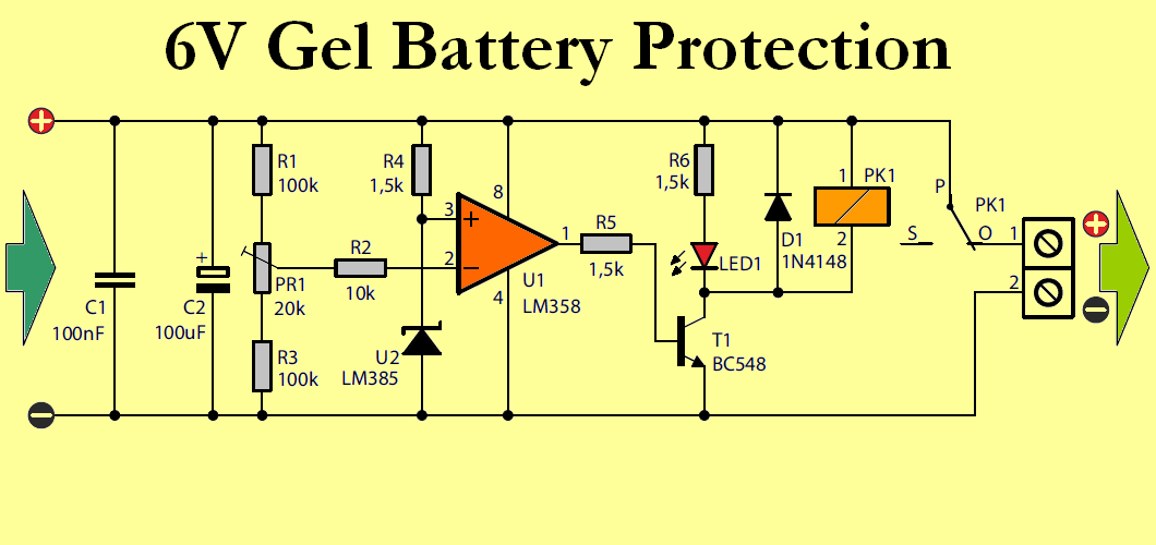
If the voltage from the divider (proportional to 6v battery voltage) is lower than the reference voltage, the comparator will change the voltage level at the output, turn on the LED and disconnect the device that is supplying power to the relay.
It needs to be calibrated without using the 6 Volt battery protection device. In most applications, the cut-off voltage is 1.75 Volts per cell, which is 5.25V for a 6 Volt battery. Using the battery below this voltage will shorten its life.
In order to perform the calibration, the device must be connected to a power supply set to the minimum battery voltage (5.25V) and the LED must be lit and the relay activated by adjusting the P1 potentiometer.
The protection circuit has a hysteresis of approximately 1V to prevent oscillations as the voltage at the battery terminals may increase when the load is disconnected. While the load disconnection voltage is approximately 5.3V, the battery voltage needs to be approximately 6.3V to be reconnected.
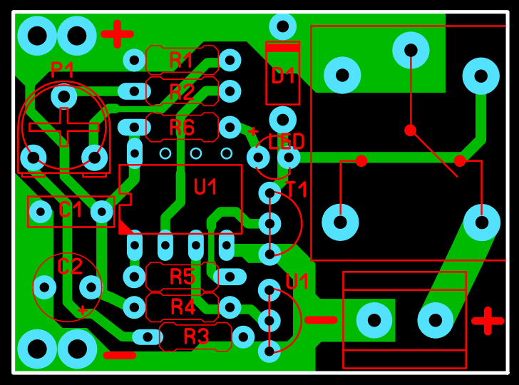
Note: PCB Drawings were prepared with Sprint Layout 6 Program. Checked but not tested.
Source: ep.com.pl/projekty/miniprojekty/11730-zabezpieczenie-akumulatora-zelowego-6-v


