The Led dimmer circuit you see in the diagram works like a DC dimmer, the brightness of a number of led groups can be increased or decreased. The supply of the circuit is + 12V and the led groups are grouped in series and parallel so as not to exceed the circuit supply. The circuit power can be supplied from a battery or directly. SW2 is the on / off switch of the circuit. SW1 switch is the switch that keeps the LEDs in continuous transmission.
Here, the task of diode D112 (1n4148) is to disconnect the signal output of the 555 timer from the circuit supply as the 555 timer will operate when the Sw1 switch is off. The function of the diode D111 (1n4148) is to protect the output of the timer. U1 555 timer is the main controller that makes the circuit work as a dimmer.
The materials RV1, R1, R2, C1 and C2 are indispensable for a timer to function properly. When the position of the potentiometer RV1 is changed, the brightness of the leds will change as the frequency at the output of the timer changes.
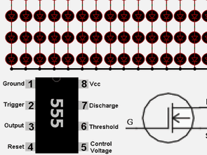
Led Dimmer Circuit Schematic Diagram
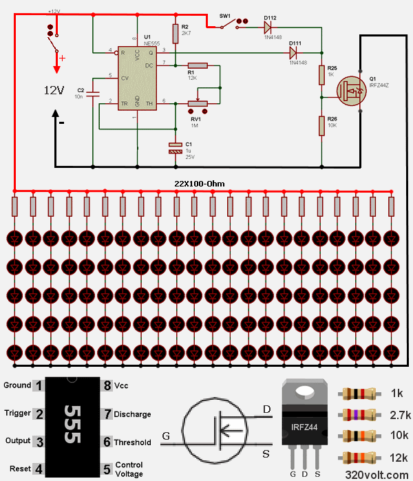
The output signal of the 555 Timer will drive the N-channel power mosfet through the R25 resistor. Resistance to R26 is the resistance that leads to power cut. In order to protect the series connected led groups, R3 ön R24 pre-resistors are connected to the anode terminals and drawn to + 12V, the cotode ends of the led groups are connected to each other and connected to the drain end of the power mosfet.
The source end of the IRFZ44 Mosfet is connected to the chassis. Depending on the temperature, IRFZ44 must be connected to the Mosfet cooler.


555 Led Gradateur Circuit IRFZ44
Le circuit de gradateur Led que vous voyez dans le diagramme fonctionne comme un gradateur DC, la luminosité d’un certain nombre de groupes de LED peut être augmentée ou diminuée. L’alimentation du circuit est de + 12V et les groupes de leds sont regroupés en série et en parallèle afin de ne pas dépasser l’alimentation du circuit. L’alimentation du circuit peut être fournie par une batterie ou directement. SW2 est l’interrupteur marche / arrêt du circuit. Le commutateur SW1 est le commutateur qui maintient les LED en transmission continue.
Ici, la tâche de la diode D112 (1n4148) est de déconnecter la sortie de signal du temporisateur 555 de l’alimentation du circuit car le temporisateur 555 fonctionnera lorsque l’interrupteur Sw1 est éteint. La diode D111 (1n4148) a pour fonction de protéger la sortie du temporisateur. La minuterie U1 555 est le contrôleur principal qui fait fonctionner le circuit comme un gradateur.
Les matériaux RV1, R1, R2, C1 et C2 sont indispensables au bon fonctionnement d’une minuterie. Lorsque la position du potentiomètre RV1 est modifiée, la luminosité des LED change à mesure que la fréquence à la sortie de la minuterie change.
Diagramme schématique du circuit de gradateur à DEL