
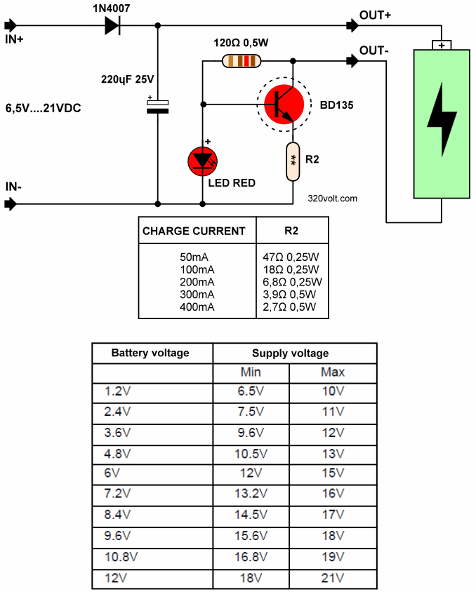
NiMH, NiCd Battery charger is a simple circuit with a single transistor and LED indicator, built with very little material. The number of series-connected batteries can be increased according to the input voltage. The charging current can be adjusted according to the emitter resistance of the BD135 transistor.
Adapter voltage selection according to battery voltage:
| Battery V | Input min. | Input max. |
|---|---|---|
| 1.2V | 6.5V | 10V |
| 2.4V | 7.5V | 11V |
| 3.6V | 9.6V | 12V |
| 4.8V | 10.5V | 13V |
| 6V | 12V | 15V |
| 7.2V | 13.2V | 16V |
| 8.4V | 14.5V | 17V |
| 9.6V | 15.6V | 18V |
| 10.8V | 16.8V | 19V |
| 12V | 18V | 21V |
Charge current (±20%) R2 resistance values:
50mA 47-ohm 1/4w
100mA 18-ohm 1/4w
200mA 6,8-ohm 1/4w
300mA 3,9-ohm 1/2w
400mA 2,7-ohm 1/2w
Battery Charger Circuit Diagram
Information provided for battery charging: It is recommended to charge and charge with a current 10 times smaller than the battery capacity. For about 15 hours. If you charge twice this current, the charging time can be halved.
Example: A 6V/1000mAh battery set can be charged for 15 hours with 100mA. If you want to charge faster, a 200mA charging current can be used for 7 hours.
Using a small charging current such as 1/10 of the battery capacity will benefit the battery life. With a small charging current, you can safely double the charging time without damaging the battery.
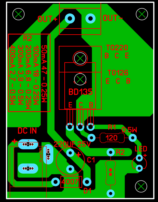
Note: The BD135 transistor used for current limiting is TO126 case, if you want to use a stronger TO220 case transistor, you need to install the transistor in reverse. PCB drawing checked, not tested
Source: cdn.velleman.eu/downloads/0/illustrated/illustrated_assembly_manual_k7302.pdf


