
The battery monitoring and maintenance device monitors the battery voltage and notifies you of the need for charging with an audible alert. It’s a simple, dual-function circuit. It maintains and improves battery performance by applying short bursts of current to the battery. The circuit, which can be permanently connected to the battery terminals, continuously monitors the battery’s condition.
Features:
Battery: 12V (including gel batteries)
Adjustable threshold voltage
Battery health indicator – LED
Low voltage audible signal
PCB dimensions: 67×43 mm
Operation of the 12V Battery Maintenance Device
The circuit is controlled by the CMOS 4541 integrated circuit, which acts as a generator. A pulse generated every minute on pin 8 produces a positive pulse lasting approximately 1 second across the 1Mohm R9 resistor. Simultaneously, the low state generated at the output of the US2A CD4093N gate (Pin 3) activates the voltage measurement circuit with the TL431 integrated circuit.
When the supply voltage is higher than the level defined by the R3 56K voltage divider, current flows through the R4 22K resistor and the TL431 integrated circuit via the R5 10K resistor. A negative pulse appears at the cathode of the TL431 for a duration equal to the time determined by the C2 and R9 elements.
This negative pulse causes the U2D gate to change state, illuminating the green LED for approximately 1 second, indicating the correct battery voltage.
The U2B gate does not change its state because it keeps the pulse output from the cathode of U3 high. However, the falling edge on the cathode of TL431 creates a short pulse on the R6 resistor. The R6 and C3 components determine the duration of this pulse (approximately 100 microseconds).
12V Battery Maintenance Device Circuit Diagram
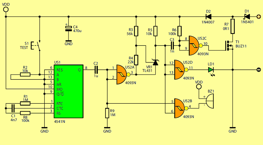
A pulse of this length appears at the gate of the BUZ11 MOSFET transistor, causing the transistor to fully open. During this short period, a strong current pulse flows from the battery through the D1 1N5401 diode, the 0.1Ω 5W R7 resistor, and the BUZ11 transistor.
However, if the battery voltage is lower than the voltage dividers R3 and R4, no current flow occurs between the anode and cathode of the TL431 during the pulse, as determined by the 1UF C2 capacitor and the 1M R9 resistor. There is no voltage drop across R5, meaning there is no negative pulse at the cathode of the TL431; it remains consistently high.
The CD4541 programming input circuit is activated by the S1 button. Normally, inputs A and B (pins 12, 13) are low, meaning the division factor is 8192. Pressing S1 reduces this factor to 256. While pulses on output Q (pin 8 U1) normally appear every minute and a few dozen seconds, after pressing S1, these pulses appear approximately every 2 seconds.
This is a manual test mode: if the battery voltage is correct, LED LD1 lights up for approximately 1 second every 2 seconds, and an audible warning is also heard if the voltage is too low. Due to pulsed operation, a 1N4007 D2 diode and a 470UF C4 capacitor are required in the power supply circuit.
Although the average current consumption is negligible, the current pulses require wide traces in the critical circuit and relatively thick wires connecting to points P and O. Ensuring perfect contact with the battery terminals is also crucial for the correct operation of this circuit.
A perfectly assembled circuit using working components will immediately function correctly. The circuit can be easily tested by connecting it to any regulated power supply. To do this, press the S1 button or short-circuit it. At supply voltages above 11V, the green LED should blink; at lower voltages, an audible alarm should sound every two seconds.
The threshold voltage, considered the discharge limit, is approximately 11V and is defined by the 5% 56k R3 and 22k R4 resistors.

Source: sklep.avt.pl/pl/products/monitor-i-konserwator-akumulatora-12v-kit-avt733-169153.html


