BJT transistor amplifier circuit 400w output transistors 4 tip41c quite strong and tip42c 4pcs 2 × 46 volts DC supply voltage + – symmetric power supply.
Output power supply AC 12 amp amp 2x33v proposed for transformer circuit connecting to the audio input volume control stereo potentiometer 10 … from 20k to do.

The transformer used in the prototype that we showed in the video is a 33-0-33 volt AC transformer, center TAP, and measure end to end brand 66 volt AC. This gives us a total power of 300W (150W) per channel. If we get the actual 400W (200W per channel), we use a 40-0-40 volt AC transformer. The reason we did the project with a lower transformer voltage was thinking of people who do not have enough money. So there would be an economic and a more expensive version that provides more performance.
Should get a transformer of a high voltage of over 45 +45 V AC and want to condition it may take a few turns of wire until you are of the appropriate voltage for this amp or better yet, build another amplifier that uses more voltage as our 500W stereo amplifier , using a transformer 55 +55 V. The ideal way to achieve a good performance of this amplifier current is 12 amps. Remember that this also depends on the transistors that use the exit. When using transistors 2SC5200 and 2SA1943, they need a minimum current of 1 amp, so we recommend using a transformer of at least 8 or 10 amps.

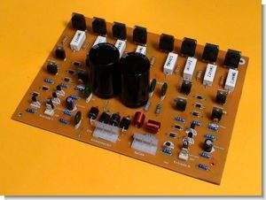
400W Power Amplifier Circuit
Source: videorockola.com Power Amplifier Circuit schematic pcb files alternative link:


100W Transistor Amplifier Circuit TIP3055
100w amp circuits 100w total output power of 50w per channel is not symmetric single source of supply for 63 volt dc supply transformer 43v ac suggested 8amp npn output transistors tip3055
Amplifier specific areas on the circuit diagram of the given values of the voltage VR1, VR2 potentiometer can adjust to these values. You can use in the supply circuit 6A10 diode or diode bridge may be ready KBU10M specified as advice uF filter capacitor 6800uF 4700uF (80v-100v) or higher (10000uF) use a value