This is a very good amplifier suitable for driving compact speakers or bass or midrange PA systems. The great advantage of this connection is, on the one hand, the use of commonly available components, reasonable price and also the integration of all basic protections directly on the amplifier board, which significantly simplifies the construction of the whole device and reduces unpleasant wiring inside. I personally built several of these amplifiers, all of them work without problems and with careful work also on the first connection.
300w amplifier Module parameters
- Input sensitivity (rms): 1V
- Input impedance: 17.8 kohm
- Output power (sine for 1kHz / 0.1% THD): 275W / 4ohms and 164W / 8ohms
- Output power (music – Burst 500Hz): 306W / 4ohms and 176W / 8ohms
- Power bandwidth (90W / 8ohm): 7 Hz – 67 kHz
- Conversion speed:> 10V / us
- Distance w / w (1W / 8ohm):> 96 dB (A)
- Harmonic distortion THD + N (20Hz – 20kHz): <0.05% for 150W / 8ohm
- Harmonic distortion THD + N (1kHz): <0.001% for 1W / 8ohm
- Intermodulation distortion (50kHz / 1kHz, 4: 1): 0.004% for 1W / 8ohm
- Intermodulation distortion (50kHz / 1kHz, 4: 1): 0.06% for 80W / 8ohm
This high-quality amplifier is equipped with Motorola bipolar transistors (ON Semiconductors) MJ15003 / 4, designed for LF applications in power amplifiers. The input part of the connection is solved by a quality operational amplifier NE5534, which is OZ with low noise and large bandwidth. It is also possible to use OZ NJM4580 or another high-quality OZ with the same connection of terminals.
OZ works as a differential amplifier. They limit the bandwidth at the input to RC members. The element R3, C5 determines the lower cut-off frequency of the amplifier at 3.5Hz, the upper cut-off frequency is set at R2, C6 at approximately 70kHz, thus preventing the penetration of the RF signal into the input part of the amplifier.
The total gain is determined by the ratio of the resistors R9 and R5 of the feedback divider. The midpoint of the divider is connected to the inverting input OZ via R4. The signal from the OZ output excites the oscillation stage with transistors T1 and T3. Their working range is determined by resistors R10 to R13 in their bases and resistors R14 and R15 in their emitters. The transistors operate in pure A class with an emitter current of 10mA, which guarantees minimal distortion. The power part is again fully symmetrical, where the excitation transistors T6 and T7 together with the end transistors T8, T14 and T9, T15 form a Darlington circuit.
300W Amplifier Circuit Schematic
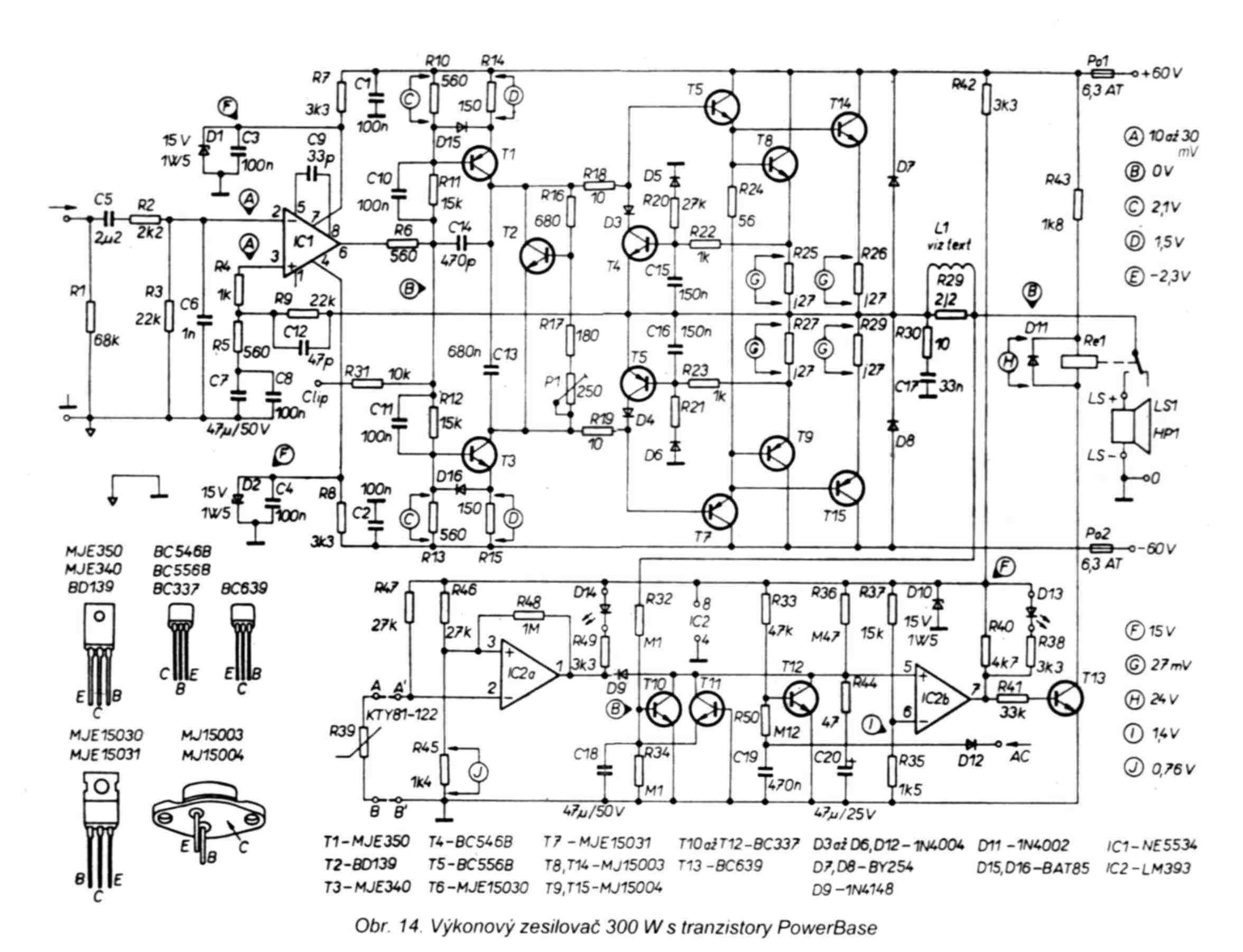
To achieve a large output power, the end transistors are connected in pairs in parallel. The output stage works in class AB, Trimmer P1 is used to set the quiescent current, which is temperature stabilized by transistor T2, which together with the divider R16, R17, P1 works as a temperature-dependent voltage source. As the temperature increases, the voltage on T2 decreases and thus the preload for the bases of exciters T6 and T7, which are therefore closed. Due to good heat transfer, it is placed on a common cooling profile. Diodes D7 and D8 protect the amplifier against peaks of opposite polarity. Resistor R30 and capacitor C17, connected between the output of the amplifier and ground, form a Boucherot cell, which creates a load for high frequencies and improves the stability of the amplifier.
The L1 choke improves the behavior of the amplifier under capacitive load and the resistor R29 in parallel with the coil minimizes the influence of the L1 inductance on signals with higher frequencies. Coil L1 has an inductance of 0.7uH and is wound on the body of resistor R29, which is at 5W. The coil has 15 turns of lacquered copper wire with a diameter of 1 mm.
The basic protection circuit of the amplifier consists of transistors T4 and T5, which protect the power transistors against current overload, eg in the event of a short circuit at the output. If an excessive current flows through the resistor R25 or R27, the protective transistor T4 or T5 opens with a voltage drop on this resistor, thus completely or partially limiting the signal of the excitation transistors and thus limiting the current through the end transistors.
Additional amplifier protection circuits consist of circuits around the LM393 comparator and provide all common protection functions, such as thermal overload protection, where the temperature is sensed by a PTC thermistor (R39) connected to the inverting input of the comparator IC2a. When the temperature is exceeded, the output of the comparator is switched and thus the load is disconnected by means of relay Re1. The error condition is indicated by the LED D14. It also provides protection for speakers against DC. output voltage.
Depending on its polarity, T10 or T11 is opened, the output of the comparator IC2b is flipped and the load is disconnected again by means of a relay. The error status is indicated by LED D13. The last function of the circuit is the delayed connection of the speakers at power-up and their immediate disconnection at power-off, thus preventing unpleasant acoustic shocks.
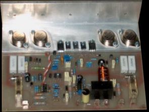
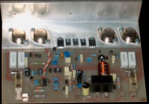
When mounting, we proceed “in layers”, ie from resistors through diodes and capacitors and finally transistors and relays. In the BOM, some types of parts are modified as available types. The aluminum profile can be purchased from the company of the seller of aluminum profiles (Alupa Pardubice, Alms Brno). Suitable size is at least 40x40mm and thickness at least 4mm. The PCB is also supplied by the Buček company for approx.
CZK 150, but the self-help production is cheaper and the quality of the boards from the Buček company is not very high. After mounting all components and checking the work, we can connect the amplifier to a stabilized power supply of about 20-30V symmetrical, preferably with a current fuse. If everything is OK, the NF part works and when the generator is connected, we can see an amplified signal at the output BEFORE THE RELAY. We will test the protection block after connecting the dc. supply voltage 60V sym.
For its correct function, we must supply the AC supply voltage from the transformer to the AC input! We also need to set the quiescent current with trimmer P1 to 100mA with each terminal transistor. There is no need to disconnect anything here, we only measure the loss on resistors R25 to R27. At 100mA, there is a decrease of 27mV on them, so we set this value approximately with trimmer P1.


Circuit amplificateur 300W MJ15003 MJ15004
Il s’agit d’un très bon amplificateur adapté pour piloter des enceintes compactes ou des systèmes de sonorisation de basse ou de milieu de gamme. Le grand avantage de cette connexion est, d’une part, l’utilisation de composants couramment disponibles, un prix raisonnable et également l’intégration de toutes les protections de base directement sur la carte de l’amplificateur, ce qui simplifie considérablement la construction de l’ensemble de l’appareil et réduit le câblage désagréable à l’intérieur . J’ai personnellement construit plusieurs de ces amplificateurs, tous fonctionnent sans problème et avec un travail minutieux également sur la première connexion.
Hello,
when unpacking it asks for a password? (LINKS-26561b.zip)
Which one do I have to enter.
Thanks and Greetings,
Andreas
Hello, 320volt.com
Hello. I need help. I have a very similar amp and the only difference I can find it has only one IC (ne5535) without the other one. If there is someone to help me tell me why this version does not have it?… I can’t find the diagram for mine, is there possibility that there we 2 versions of PA 300? Im plannig to use it for sub woofer our studio is missing…
Uploaded picture: https://ibb.co/dBqzBXd