I’ve always thought about building a nice 2.1 amp circuit. The funny thing is, despite being a hobbyist, there aren’t any good projects online. There are plenty of mono and stereo amplifiers, but there doesn’t seem to be any 2+1 amplifier circuits.
I used the famous LM3886 amplifier IC from National Semiconductor for the bass level. For the filter, I used a 4558 op amp and the R-L output, also from National Semiconductor. These two are excellent, both in terms of performance and sound quality.
I was pleased with the sound quality during the tests, especially the bass. Despite my small room and the many factors that could distort the sound, it worked quite well. The LM1876 output is quite high, and using it with a large cabinet would be much more effective.
The quality is somewhat noticeable in the test videos, but the sound is quite distorted due to the poor camera quality. It still gives you an idea. I’m satisfied. These two ICs have proven themselves, and the manufacturer’s sample schematic didn’t deviate too much from it. 😉 Also, the volume of the MP3 player I use isn’t very loud, but the sound is quite loud. It was high.
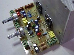
The coil on the 10 ohm 2W resistors at the R-L- outputs can be made by wrapping 13 turns of 1mm wire around a pencil. Note that two 1.5nf wires were not used against the casing at the audio input.
Printed circuit board, top view and material values;


Read the tested circuit;


I completed the circuit today. The schematic is being prepared, and if I can finish it without getting bored, I’ll share it. The circuit works perfectly. Pay attention to the thin traces in the LM1876 section during construction. Make sure there are no shorts or breaks on the PCB. That’s all for now…
Update; Questions and Answers
Since I’m not a habit of reading comments 🙂 I’m adding the questions and answers asked in the comments to the article 😉
Hakan says: September 3, 2011, 11:18
Hello,
How much efficiency can I get from this circuit if I run it with a symmetrical 12-volt, 90-watt transformer?
Good work.
gevv says: September 3, 2011, 12:37
At least 2x15v 150w…200w transformers are required.
doğan can sönmeyen says: September 13, 2011, 10:08
As-Salamu alaykum, master, could you tell me what wattage of bass and speakers we need?
gevv says: September 13, 2011, 10:33
The LM3886 gives 68w, the LM1876 gives 2x20w, but if these values are the actual musical power, the LM3886 gives 130w, and the LM1876 gives 2x35w.
You can use speakers with an RMS of 100w for bass and an RMS of 30w for R-L, but the speakers really need to have the power listed on them. Low-quality, cheap ones usually don’t list the actual power.
kayahancakir says: September 28, 2011, 9:08 PM
Will it not work at all with a 2×12 volt supply? Please help.
gevv says: September 28, 2011, 9:14 PM
It works, but you can’t get full power, but it’s still manageable. For example, if the LM3886 outputs 68W rms with 2x25V, it outputs 30W with 2x12V. Of course, these values aren’t guaranteed, but the power will definitely be lower.
First of all, hello. Are the 1k and 10k resistors next to the LM3886 IC and the two 33k resistors next to the 4558 opm-amp supposed to be SMD resistors? Will they be mounted as SMD resistors? Could you help me? Or will those spaces be left empty?
You can use regular resistors instead of the SMD resistors. I wrote that I used SMD type resistors, I said “I used them” but there are those who say “Do we use them, is it left empty?” etc. I don’t know how to say it more clearly, the materials with values written on them as seen in the material layout were used, only 1.5nf SMD capacitors were not used, I explained them in the article.

Updated May 2, 2013
I’m adding a printable PDF version of the PCB drawing. I copied this drawing from the image file I added to the post because I couldn’t find the source PCB drawing. I checked to see if it was missing. The original drawing was copied, but please check it against the image.


10 LED VU Meter Circuit LM3915
In this article made with LM3915 integrated LED vu meter is shown in Figure 10 . VU meter circuit feature , listened to music according to the severity of the LEDs are lit . So vu meter circuit indicates the level of severity of music . Music of the bass, treble and volume regardless of how much more so the LEDs are lit.
Circuit at the same time the volume is more or less well understood. The first seven green LEDs on the circuit , while the other three LEDs make the dream of red renktedir.b the following purposes ; Green LED illuminates when the normal volume , together with the red LED lights up in green when the sound intensity is more straightforward.
LM3886 LM1876 2+1 Hi Fi Amplifier Schematic Diagram Missing. Please Upload Schematic.