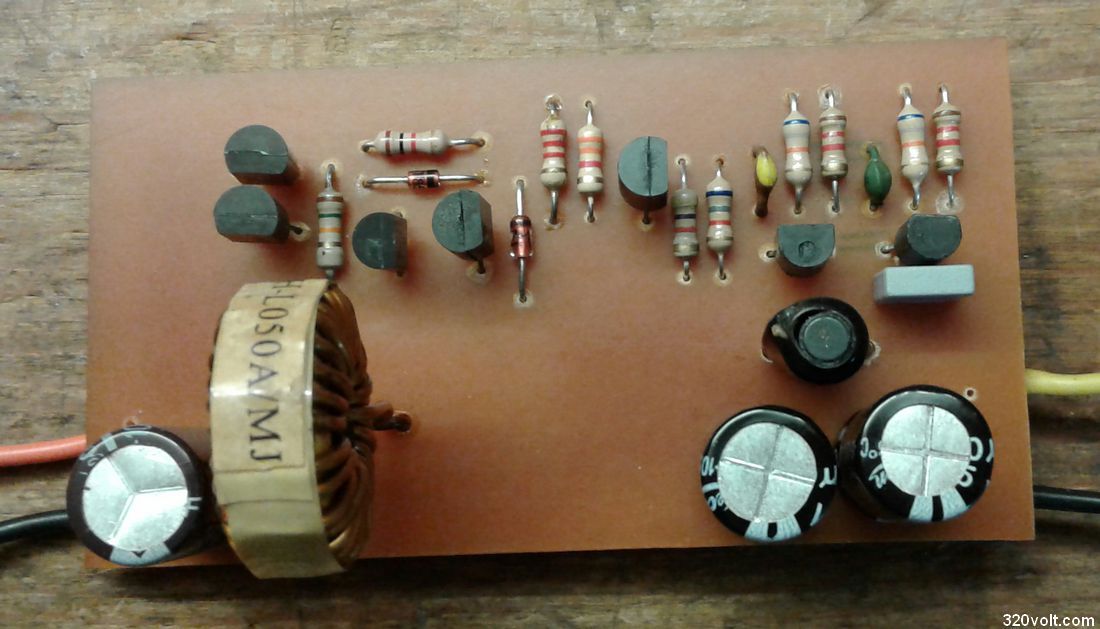
I did not like the PCB design of this application of Elektor and rearranged it myself. 🙂 There is even another variation of the same scheme on the site.
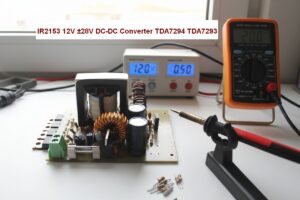
(12 Volt 24 Volt DC DC Converter Circuit BUZ11)
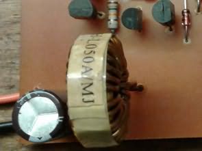
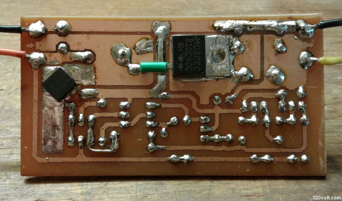
The aim is to make the circuit board smaller and get rid of the heat sink issue. That’s why I mounted the two heated elements from the solder surface and left enough copper surface area for them to cool. Even under full load, the part that gets heated the least is the mosfet, the schottky diode gets hot more, and the part that gets hot the most is the coil.
Although the circuit operates in a range of 40 kHz, the designers chose a BF series element in the oscillator part, I will not object to what they know, but I used BC547 instead in my own application, there was no problem. You can also use commercially available KTC9018 or its equivalents.
It is not necessary to have the same transistors specified in the diagram, you can try equivalent ones that come to your mind. We will try to answer any questions you may have. Just pay attention to the foot connections.
12V DC to 24V DC Circuit Diagram
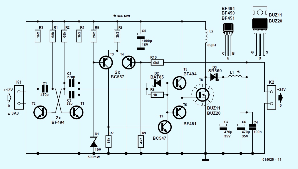
The element I removed from a broken PC motherboard was used as the Mosfet (AOD412 N-Channel). The Vds value of the mosfet should be at least 30V because there are also ones around 18-20V on PC motherboards. Schottky diode and coil were taken from a PC power supply.
The output current is stated as 1.5 Amperes at most, but in my experiments I was able to get 2 Amperes with a very small voltage drop, and even 3 Amperes with a few volts drop.
By changing the value of the resistors on the base leg of the transistor, designated as T4 in the diagram, the output voltage adjustable feature can be added to the circuit, and I even tried it.
Adjustment was possible by connecting a trimpot to this point. However, I would like to point out that I see this as an experimental feature because when I changed the voltage, some problems occurred under load.
That’s why inexperienced friends should not trust this setting option, but you can still tinker with it for testing purposes to learn.
Do not connect your expensive devices to the output, I will not be held responsible.
Stone resistors with large wattages or high wattage bulbs such as 24 – 36 volts can be installed to test. Of course, it is even better if you have an electronic load device.
12V DC to 24V DC PCB and source files;