1KW PFC Circuit UC3855 for its function requires a dc supply voltage of 10 to 20V . His sampling is during normal operation of 17 to 25 ma. The integrated circuit additionally contains the input VCC zener diode of 20V. The maximum current for this diode is, however, only 20 mA [19]. Therefore, it is safer for the diode not to take advantage i.e. to stabilize the supply voltage externally at the level of the lower than 20V.
1000W PFC Circuit Schematic UC3855
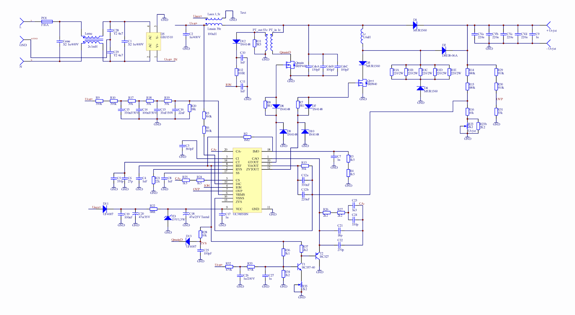
For the power supply of the integrated circuit will be selected, a voltage VCC = 15V. This voltage is sufficiently low compared to the limit of 20V, so the risk of damage to the circuit UC3855 is minimal. At the same time the voltage 15V is sufficient for fast and reliable control of switching transistors – when VCC = 18V is output the control voltage for the transistors type. It can be assumed that at UCC = 15V reaches the border of the 10V needed for the complete switching of the switching transistors . It will be used variant of the circuit UC3855BN, which has a limit of power on 10.5 V (as opposed to a variant of UC3855A
![]() 1000w pfc circuit pcb schematic all files alternative links:
1000w pfc circuit pcb schematic all files alternative links:
FILE DOWNLOAD LINK LIST (in TXT format): LINKS-25671.zip


Digital Class D Amplifier Circuit TAS5706A PCM1850A ATmega128
TAS5706A Class D Amplifier was itself the signal processor. From this parts depend all the other elements. Has an impact on the type of power supply, the control method of the type converter. That is why he was first selected DSP processor.
There are more firms that produce the processed signal processors whose internal connection is possible in many ways to reconfigure. However, the need was that the management was as simple as possible, therefore, programmable signal processors are discarded from consideration. Was selected processor TAS5706A from the company Texas Instruments. TAS5706A is a digital signal processor with fixed elements*1 and integrated by the final degree class D.
1000W PFC-Schaltung UC3855
1KW PFC-Schaltung UC3855 für seine Funktion benötigt eine dc-Versorgungsspannung von 10 bis 20V . Seine Probenahme ist während des normalen Betriebs von 17 bis 25 ma. Die integrierte Schaltung enthält zusätzlich die input VCC zener-diode 20V. Der maximale Strom für diese diode ist, jedoch nur 20 mA [19]. Daher ist es sicherer für die diode nicht zu nutzen, D. H. zur Stabilisierung der Versorgungsspannung extern auf der Ebene der niedriger als 20V.