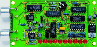
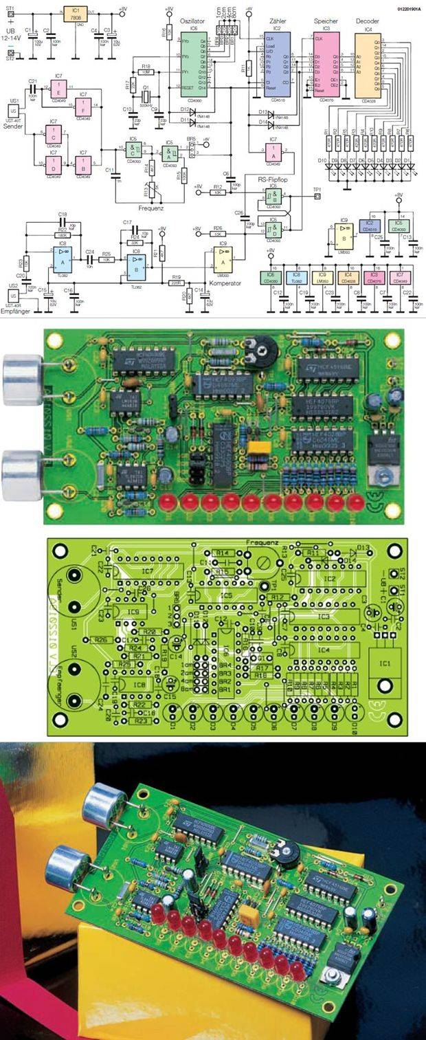
Ultrasonic distance meter, ultrasonic parking sensor and opamp CMOS integrated circuit representation on the board from two ultrasonic receiver circuit with LEDs used and UST-40 UST -40T
Distance measurement using ultrasound is already widely used. We provide an easy to implement distance measurement and display circuit, is universally applicable. About an LED chain is the distance before a Ultrasonic sensor located opposite stand.
When one thinks of the convenient “contactless” Measuring distances falls, sure almost every first “radar” a, a distance measuring method since the standard in the Air and Shipping is to distances and To determine speeds. For a short However, distances has in the past 20 years ultrasonic measuring method established that much easier and is to implement cost-effective and also not with high-energy radio waves works.
Ultrasonic Parking Sensor Project
Source: http://www.elv-downloads.de/service/manuals/UAM1/46178_UAM1_km.pdf Ultrasonic Distance Meter Circuit files alternative link:


Power LED Dimmer Circuit
Quality and stable LED dimmer circuit LM358 and LM393 opamp based upon power on the floor BUZ71 MOSFET used operating frequency 150kHz brightness and delicate light can be controlled LED dimmer circuit operating voltage of 12 volts, 24 volts max. 1.5 amps
Dimmer for LED modules
With modern LED orders can be many light and lighting effects. Especially in bright LED configurations such as cluster or LED Stripes, is the question of the possibility of Dimmens the brightness of these orders. Our little dimmer project addresses precisely this task. The pulse width scheme , the control electronics almost . About one can Comp also an external potentiometer brightness setting to be connected, so that the operation locally separated from the actual control electronics can make.