You know a circuit that destroys and removes harmful things such as crustaceans, moths, single-celled organisms, parasites, etc. that stick to the hull of the boat, wooden parts, and engine propellers with ultrasonic signals, like ultrasonic mouse repellent circuits 🙂 this circuit is designed for boats, the frequency range and power are adjusted according to the boats.
It will be very useful for boat owners, and it is a good source for people interested in pic programming in subjects such as ultrasonic signal generation with pic, etc.
Ultrasonic Anti-Fouling Unit for Boats
Algae on the hull is a problem for all boat owners. If left unchecked, it slows the boat down significantly, and if it is a speedboat, it leads to great increases in fuel consumption. If it is a yacht, it will slow it down, make it less maneuverable, and become very heavy. The solution is to take the boat out of the water every year and spray it with water and scrape off all the growth, and then cover the hull with toxic anti-algae paint.
Overall output frequency range: 19.08kHz to 41.66kHz in 14 bands; frequency overlap included between each band
Frequency sweep in each band: 12 frequencies ranging from approximately 80Hz steps at 20kHz to 344Hz steps at 40kHz
Signal burst duration: 600ms at 20kHz, 300ms at 40kHz (1000 cycles/burst)
Pause between each band: 500ms
Dead time for push-pull driver: 5µs
Output driver: 250VAC (up to 800V peak-peak)
Low voltage threshold: 11.5V (turn-on voltage = 12V)
Supply voltage: 11.5 – 16V maximum
Current drain: 220mA average at 12V with 3.6nF load
Peak current at converter resonance: 3A
Quiet current below 11.5V: 6.7mA
A Everyone knows that owning and maintaining a boat is expensive; the larger the boat, the more expensive it is.
Many readers will be familiar with trailer sailboats and motorboats. They are relatively cheap to run and, since they are not left in the water, they never have problems with seaweed. However, when you have a boat that is rocking or tied to a dock in salt water, seaweed is endemic and the warmer the water, the more serious the problem.
Electronic Anti fouling Circuit Ultrasonic

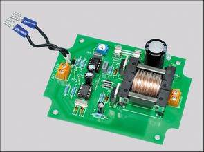
Ultrasonic Anti fouling circuit uses tl499a, pic12f675 integrated circuits, works with 12 volt dc, FTD29 transformer is used for the driver of the ultra sonic transducer (piezzo sonic speaker), ETD29 can most likely be used instead, transformer winding details are explained with pictures.
PIC12F675 Software is written in assembly language, source .asm, .hex codes, pcb printed circuit, circuit diagram box dimensions, oscilloscope measurement graphs are available.
Transducer piezzo sonic speaker version voltage is very high, 250v…800v ac circuit tests, do not touch the transformer output while working, it is dangerous
Finally, maybe the frequency of the circuit can be changed and an ultrasonic fouling circuit can be used for pests and insects in homes and gardens 🙂
Source: http://www.siliconchip.com.au/cms/A_112107/article.html Anti fouling project alternative link:


Quality Microphone Preamplifier Circuit AD-8648 Op Amp
Microphone preamplifier circuit 5 volts to 20 volts dc voltage is working with measurements, operating characteristics quite well Circuit AD8648-ARZ SMD Op-amp based on the printed circuit board design is very good as is the practice of aluminum cans for supply and 9v alkaline is used very good results. Preamplifier Circuit 0-014% power supply 5v…20V DC
Microphone Preamplifier Circuit