Circuit based on tda 2030 amplifier integrated tda2030 lm1875, tda2040, tda2050 can be used instead of lm1875, tda2040, tda2050 pcb design is very small for sound control, a potentiometer is added to the supply filter capacitor on the pcb, the bass filter made with tl074 can be used in different amplifier circuits.
The system is equipped with an active filter built on operational amplifiers and a combiner that allows the signal to be fed simultaneously from the stereo output. Since the signal for the system is taken from the speaker outputs of an already working sound system, there is no need to interfere with the working amplifier. There is another advantage of getting the signal from the speakers, that is, it allows you to maintain a constant ratio of the volume of the Subwoofer to the stereo system.
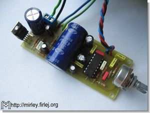
The gain of the woofer channel can be adjusted with a potentiometer. After filtering out the high frequencies, the signal is amplified using the TDA2030 or similar. The board is designed to enable the TDA2030, LM1875, TDA2040 and TDA2050 systems to work (after replacing common elements). This gives you the ability to adjust the output power to your liking and your amplifier. The device was created as a supplement to the 2x15W Amplifier project, so the shape of the board matches the length of the previous one. In the announced project, the TDA2040 system works successfully by powering the Tonsil GDN 30/60/1 woofer.
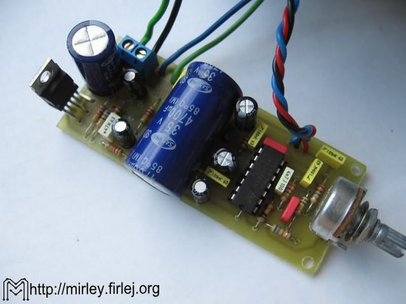
TDA2030 Subwoofer Amplifer Circuit

The stereo input signal is fed to the Input (gold pin) connector using C1 (100nF) and R1 (2.2M) on the first channel and C2 (100nF) and R2 (2.2M) on the second channel. input inverter amplifier U1A (TL074). The P1 potentiometer (220k) working in the feedback of the U1A amplifier allows you to adjust the gain of the whole system. Then the signal is fed to the second order filter with elements U1B (TL074), R3 (68k), R4 (150k), C3 (22nF) and C4 (4.7nF) working as Butterworth filter. Through the circuit C5 (220nF), R5 (100k), the signal goes to the follower U1C, and then through C6 (10uF) to the input of the power amplifier U2 (TDA2030).
Capacitor C6 provides separation of the DC component of the preamplifier from the power amp. Resistors R7 (100k), R8 (100k) and R9 (100k) are used to polarize the preamplifier stages, and capacitor C7 (22uF) filters this bias voltage. Elements R10 (4.7k), R11 (150k) and C8 (2.2uF) operate in a negative feedback loop and are designed to shape the spectral characteristics of the amplifier.
Resistor R12 (1R) works together with capacitor C9 (100nF) in a system that shapes the output characteristics. Capacitor C10 (2200uF) prevents constant current flow through the speaker, adjusts the lower cutoff frequency of the entire amplifier along with the impedance of the speaker.
Diodes D1 (1N4007) and D2 (1N4007) prevent the appearance of dangerous voltages in the speaker coil. A supply voltage of 18 – 30V is applied to the Zas connector, capacitor C11 (100uF or 4700uF) is the main filtering capacitor. The U3 stabilizer (78L15) together with capacitors C12 (100nF), C15 (100uF) and C16 (100nF) provides a 15V supply voltage for the U1 system.
Elements R13 (10k) and R14 (10k) and capacitors C13 (100uF) and C14 (100nF). They form a divider that polarizes the inputs of the operational amplifiers with a voltage close to half their supply voltage.
Source: elektroda.pl TDA2030 Subwoofer Amplifer Project schematic pcb files alternative link:


Adjustable 0-5A 0-50V Laboratory Power Supply Circuit LM723
Adjustable power supply voltage regulator Ua723 integrated circuit based on the LM723 can be used in place between 0:50 volts 0.5 amps of current and voltage can be controlled over current and short circuit protection circuitry has long been ar umarımyap opportunity I can find. ‘ll Use the power transformer should be at least 5 amps and 36 volts AC output voltage
Note: 4700 uF capacitors used filter suggestion or 10000uF, 6800uf
Laboratory Power Supply Circuit