LM3886 Amplifier integrated is very popular, many applications have been made, I made a special design and I am sharing it.
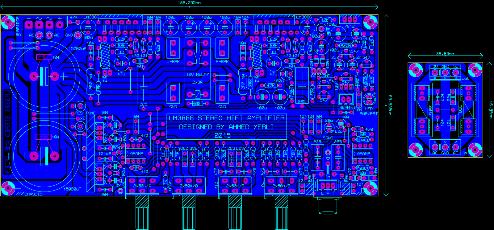
First of all, there are differences between the photos and the pcb, some because of the material values I have and some because they are in the development phase. You should take the PCB drawing as basis.
Value for res: (Vamp-20V)/70mA power, (Vamp-20V)x70mA
Value for res tone: (Vamp-20)/30mA power, (Vamp-20V)x30mA
Amplifier feeds should be selected according to the speaker impedances given in the LM3886 Datasheet and these resistances should be calculated accordingly.
The + and – feed paths, speaker lines and leads must be covered with solder.
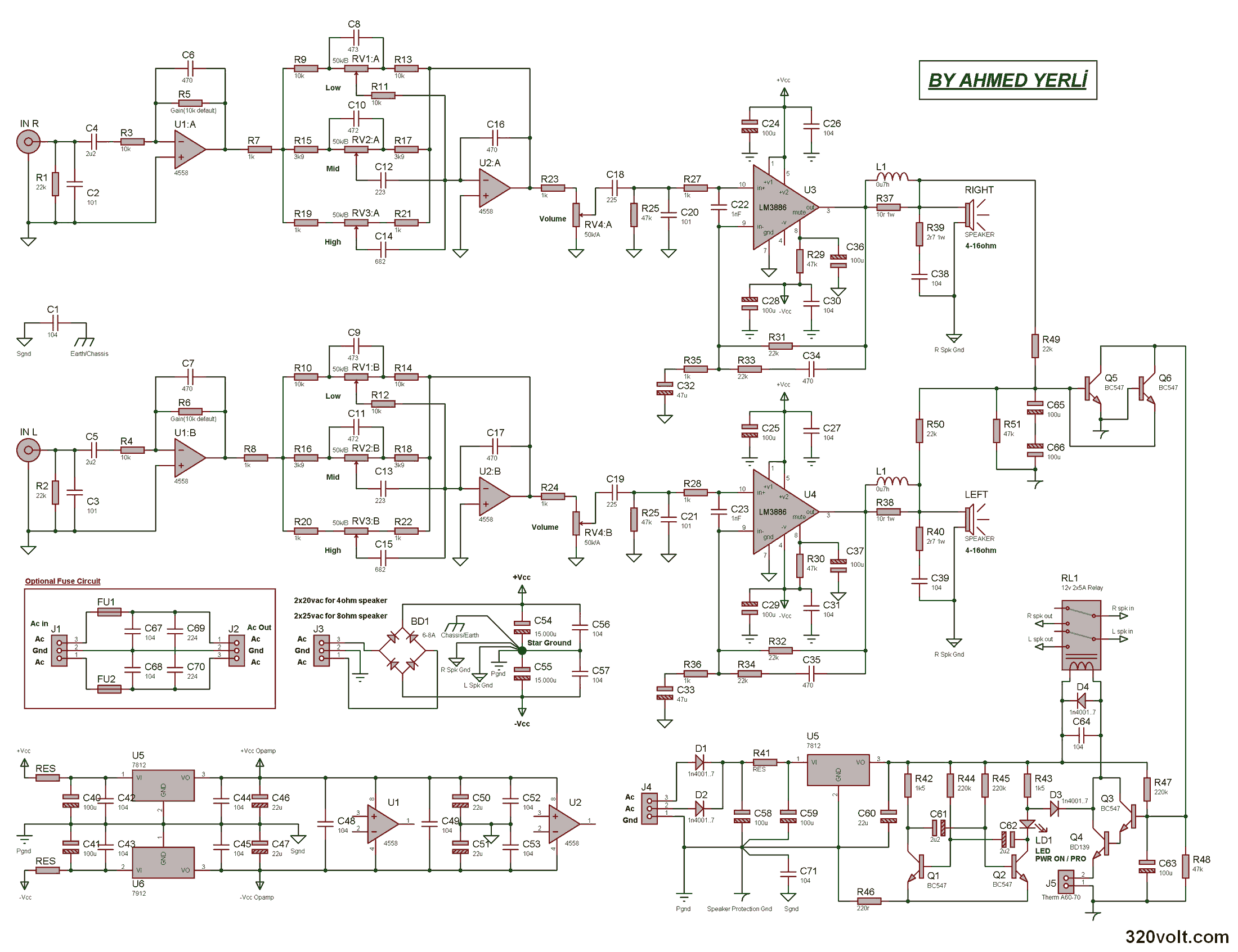
Rgain resistors can be chosen according to preference between 10-15K. My suggestion is 10kohm.
The coil on the output leg of the LM3886, i.e. leg number 3, fit 10 turns of 1.2mm wire onto the resistors, my resistors were 2W, so I used it this way.
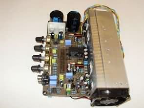
LM3886 Amplifier Project
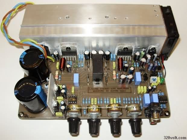

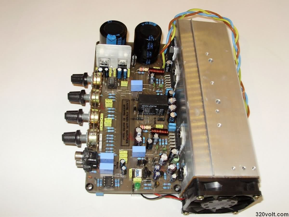

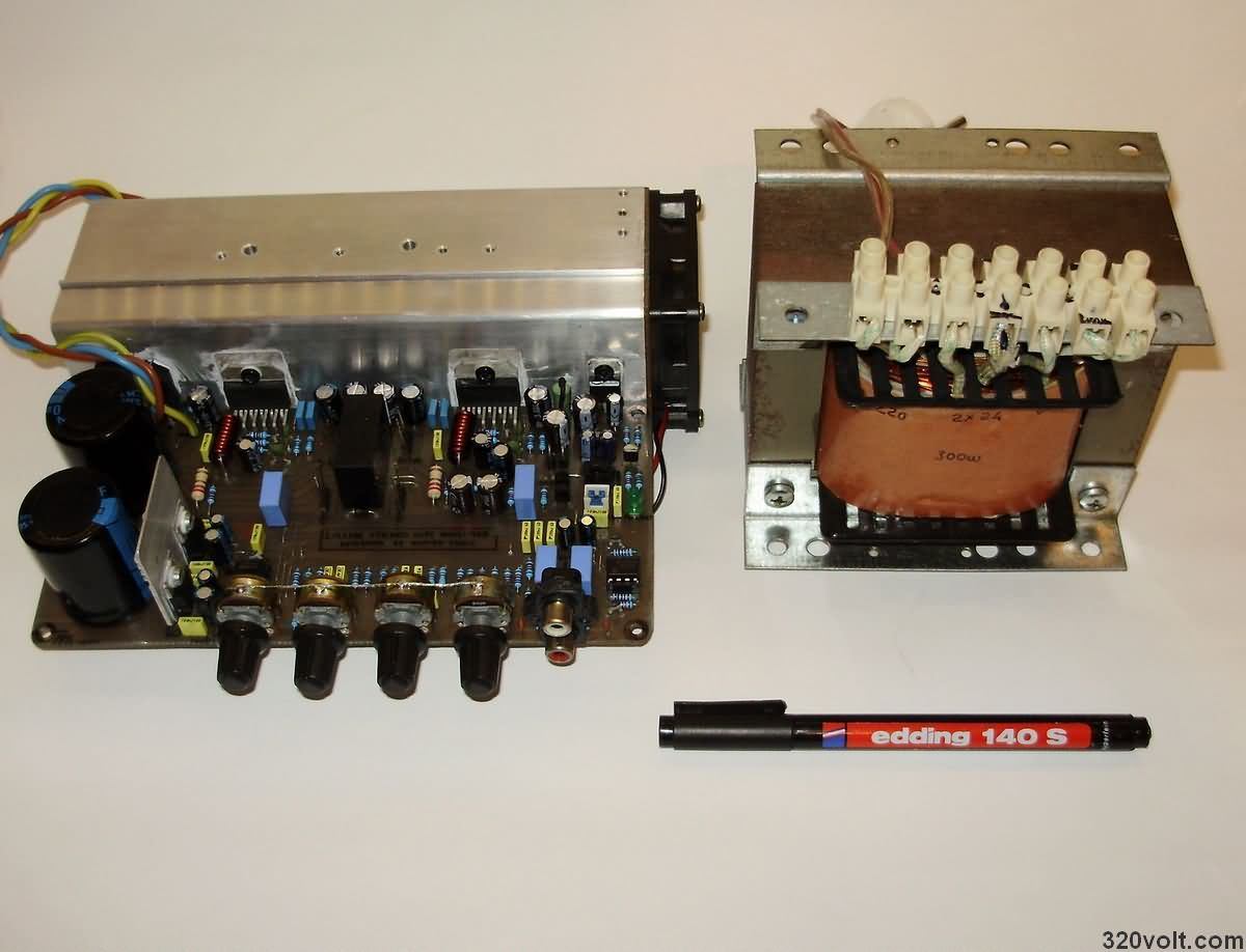
I used a cooler for the tone control regulators, the main purpose of which is to act as a shield between the capacitor (15000uF) and the opamps. Therefore, it must be connected to the gnd line.
If a metal box is to be used, which is my recommendation. A connection must be made from the places marked “chassis” in the circuit to the box with metal card holders or cable (the one on the left should be thick, 1-1.5mm2). There is no need to connect the pots to the GND line on the circuit in the metal box. Except for metal, it must be connected to GND. Likewise, LM3886 coolers should be connected to the star chassis if there is no metal box.
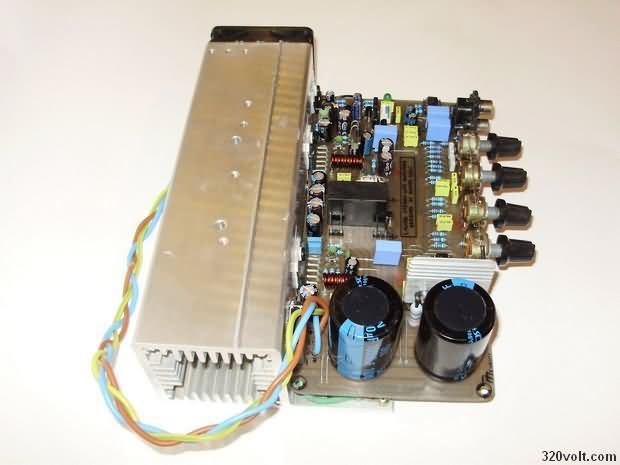
Speaker protection and main supply AC cables should either be braided as shown in the pictures or shielded cables should be chosen (especially for speaker protection).
Apart from this, I recommend using the fuse PCB. If not used, it would be nice to add capacitors between ACs.
Therm A:, Lm3886s normally have heat protection, but a thermostat can also be used as additional protection (optional). In this case, a 60-70 degree thermostat that is normally closed, that is, passes current when cold, can be used. If not desired, that section should be short-circuited.
Some jumps on the PCB are drawn thicker and thicker wires should be connected to these places. 0.8-mm recommendation.
Bridge diode 6-8A (KBU10M, KBU8M etc.) can be used.
Lm3886 Stereo Amplifier Project pcb files:


Raspberry Pi CD-ROM mechanics with Plotter
The mechanical part of the project Plotter plotter as plotter module contains a CDROM is made up of parts used to control the power of the engine is provided with the Raspberry Pi. Wireless computer communications is done via SVG plotter plotter all supported image formats that belong to the block of the source code of the project schema files in module Raspberry Pi
Plotter project
Stereo-Verstärker-Projekt mit LM3886
LM3886 verstärker ist eine sehr beliebte Anwendung, die ich gemacht habe, ein benutzerdefiniertes design, das ich getan habe, Teile ich es.
Gibt es Unterschiede zwischen der Leiterplatte in Erster Linie mit Fotos, einige der das material in meiner hand, weil einige Werte in der Entwicklungsphase. – Sie bekommen basiert auf der Zeichnung von der platine.
There is no pcb circuit design layout in pdf so if you have circuit pdf file plz send me in drive
Hello,
You can convert .xps file to .pdf format.