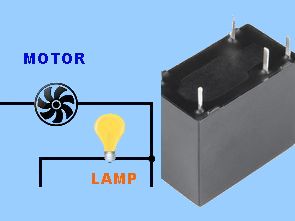
In SPDT spdt relays (Single Pole Double Throw SPDT Relay) are very useful in some applications due to its internal configuration. It has one common terminal and 2 contacts in 2 different versions can be normally closed and the other opened, or it may be normally open and the other closed. So basically you can see the spdt relay as a way to toggle between 2 loops: when there is no voltage at the coil is one circuit receives current, the other is not and when the coil gets voltage is reversed.
SPDT relay circuit schematic
Contents
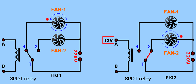
How SPDT relay work?
In Fig. 1 the DC voltage is supplied to the coil so the terminal T is connected to contact 1 therefore the current can flow through the fan 1 and it cannot flow through the fan 2.
In Fig.2, When the DC voltage is supplied to the coil and the terminal T is now connected to pin-2, so that current does not flow through the fan 1, but now it flows through the fan-2.
DPDT relay
In dpdt relay (double-pole two-position) is quite interesting and can be used in various ideas, including changing the direction of movement of the engine, as you can see in the picture below. It has 2 terminals and connectors 4 and you can look at the dpdt relay as the equivalent of 2 SPDT relays.
To switch between the 2 different loads with dpdt switch
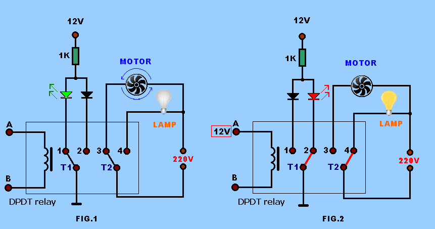
we can use a dpdt switch to select between the 2 different loads, and also have a visual indication that the load is connected. In our case (Fig. 1) when there is no voltage at the coil the fan and green led turn on . When we apply voltage to the coil (Fig. 2) the relay switches its contacts and now the light buld and the red led does not turn on.
To change the direction of rotation of the motor with a dpdt relay
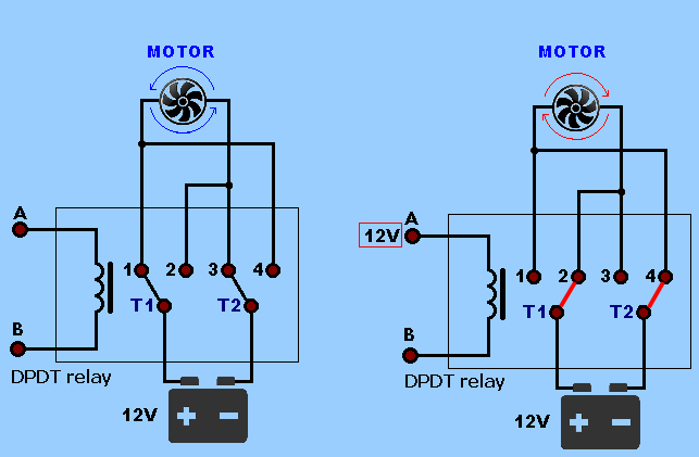
As you can see in the schematic diagram with 12V battery (or use other voltages) connected to the plus terminal T1 and minus terminal T2. Contacts 1 and 4 connected to 2 and 3 too.
Without voltage applied to the coil to positive battery connected to pin-1 (and-4) and minus 3 (and-2) so that the motor rotates in one direction (say clockwise). When voltage is applied to the coil of the relay switches and now T1 (+plus) is connected to pin 2 (and-3) and T2 (-minus) connected to 4 (and-1), so the motor changes direction of rotation.
What is this SPDT DPDT SPST DPST relays
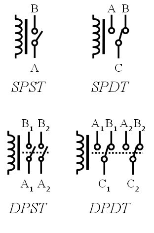
SPST Single Pole Single Throw. These have two terminals which can be connected or disconnected. Including two for the coil, such a relay has four terminals in total. It is ambiguous whether the pole is normally open or normally closed. The terminology “SPNO” and “SPNC” is sometimes used to resolve the ambiguity.
SPDT Single Pole Double Throw. A common terminal connects to either of two others. Including two for the coil, such a relay has five terminals in total.
DPST Double Pole Single Throw. These have two pairs of terminals. Equivalent to two SPST switches or relays actuated by a single coil. Including two for the coil, such a relay has six terminals in total. The poles may be Form A or Form B (or one of each).
DPDT Double Pole Double Throw. These have two rows of change-over terminals. Equivalent to two SPDT switches or relays actuated by a single coil. Such a relay has eight terminals, including the coil.


Flowcode Examples
Flowcode pic programming pic about the program in the form of flow diagrams of the easiest programs you can write easily in the market, still us is very simple, although it was touted as easy a little bit microcontroller, code, etc. there must be a free expression of information can be solved by the application of very video though, especially as a hobby Flowcode v4 Flowcode programming pic with most of the samples prepared with an ideal program for those
SPDT-Relais und DPDT-Relais
In SPDT spdt-relais (Single Pole Double Throw-SPDT-Relais) sind sehr nützlich, in einigen Anwendungen aufgrund Ihrer internen Konfiguration. Es hat eine gemeinsame Klemme und 2 Kontakten in 2 verschiedenen Versionen können Sie in der Regel geschlossen und das andere geöffnet, oder es kann normalerweise offen und die andere geschlossen. Also im Grunde können Sie sehen, die spdt-relais als einen Weg, der zum Umschalten zwischen den 2 loops: wenn es keine Spannung an der Spule ist eine Schaltung erhält Strom, der andere nicht und wenn die Spule bekommt Spannung Umgekehrt wird.