Solenoid valves are devices widespread in industry and outside. The indisputable convenience of use is paid for by the considerable power consumption of the coil, which – obviously – heats up to a significant temperature, while high force is needed only during the movement of the core in the electromagnet. The presented system allows to eliminate this problem.
The schematic diagram of the proposed solution is shown in image. The multivibrator made on the operational amplifier A of the TL084 system generates a square wave with a frequency of about 23kHz. This signal is integrated by a circuit consisting of a resistor R5 2.7K and a capacitor C3 22UF – the voltage waveform on the latter is close to triangular. Similar, because in fact the slopes are exponential, but this deviation does not change the principle of the system’s work.
Schematic diagram of the solenoid coil power regulator system
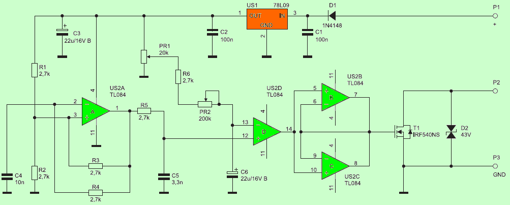
In turn, the PR1 potentiometer sets the maximum voltage to which the C6 capacitor will be charged, while PR2 together with the R6 resistor determine the time constant of such a circuit. The US2B and US2C amplifiers are connected as voltage repeaters and act as the stage controlling the gate of the T1 IRF540 MOSFET. Diode D2 contains voltage pulses that could damage the transistor.
The operation is as follows: for a moment after turning on the power, the comparator “compares” the quasi-triangular waveform to a voltage close to 0V, which is on the covers of the discharged C6 capacitor. The result of this comparison is the appearance of a voltage close to 9 V at the output of the operational amplifier working in an open feedback loop. Transistor IRF540 T1 is completely open. As voltage increases on C6, the IRF540 transistor’s gate gets a rectangular waveform with decreasing filling. The minimum filling value is set by the PR1 potentiometer mentioned above.
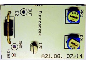
All elements, except potentiometers and US1 78L09 stabilizer, are surface mounted. A correctly assembled system does not require any startup operations, except for the experimental setting of the position of the PR1 and PR2 potentiometer final filling: from 0 to 100%, time to start switching the T1 transistor: from tens of milliseconds to about 4s.
When setting the minimum fill with the power on, keep in mind that the system response will be delayed due to the need to charge or discharge C6. Discharging this capacitor after disconnecting the power supply takes several seconds – it is worth remembering when setting the PR2.
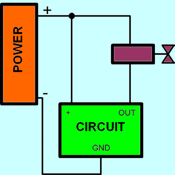
The system supply voltage should be in the range of 12V … 35 V. The current “consumed” by the device does not exceed 10 mA. The controlled solenoid valve should be adapted to be supplied with a constant voltage of not more than approx. 40 V, with a current consumption of up to approx. 4A. The correct connection arrangement is shown in figure 3 assuming that the supply voltage does not exceed the maximum value for the 78L09 IC.
![]()
FILE DOWNLOAD LINK LIST (in TXT format): LINKS-26312.zip


Circuit de réduction de puissance de bobine de solénoïde
Les électrovannes sont des dispositifs répandus dans l’industrie et à l’extérieur. La commodité indiscutable de l’utilisation est payée par la consommation d’énergie considérable de la bobine, qui – évidemment – chauffe jusqu’à une température importante, alors qu’une force élevée n’est nécessaire que pendant le mouvement du noyau dans l’électro-aimant. Le système présenté permet d’éliminer ce problème.
Le diagramme schématique de la solution proposée est montré dans l’image. Le multivibrateur réalisé sur l’amplificateur opérationnel A du système TL084 génère une onde carrée avec une fréquence d’environ 23 kHz. Ce signal est intégré par un circuit composé d’une résistance R5 2,7K et d’un condensateur C3 22UF – la forme d’onde de tension sur ce dernier est proche de triangulaire. Similaire, car en fait les pentes sont exponentielles, mais cette déviation ne change pas le principe du fonctionnement du système.
Diagramme schématique du système de régulateur de puissance de bobine solénoïde