The Jtag Isolator device is intended for designers working with devices supplied with voltage dangerous to life or at a potential much higher than the potential of the earth.
In the JTAG isolator, the connector on the programmer’s side is 10-instead of 6-pin and fits the JTAG output, which also contains ISP lines in the Dragon programmer, similar to Dragon Safe. In addition, due to the fact that the 74HC125 buffer system contains only four gates, the Reset line is not buffered, only the U7 optocoupler is isolated, while the TMS line is buffered not used in ISP mode.
Due to the high speeds of the JTAG interface, it is recommended to use 6N137-E optocouplers operating up to 10 MB/s (in AVR the maximum JTAG speed is theoretically 5 MB/s), but by agreeing with a lower speed, 6N137 optocouplers (1 MB/s can be used ).
Schematic diagram of the JTAG isolator
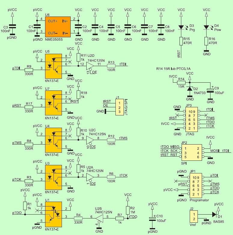
The isolator circuit has protections such as programmer. Jumper J1 is set depending on the mode of operation in the position JTAG (2-3 pins shorted) or ISP (shorted pins 1-2). Setting the jumper in the JTAG position when working in SPI mode will cause that the interface lines will not be disconnected after programming, which will prevent their use by the microcontroller for other purposes.
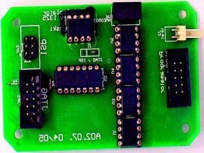
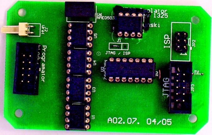
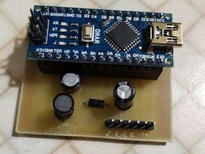
Installation is typical and does not require discussion, just remember to install five jumpers. We also need to decide if we mount the U6 converter or power the optocoupler from the J2 connector. It is worth using a base for the U2 system. I do not recommend “ordinary” stands, which lose their properties over time. In my constructions I use precise stands, so-called tulip stands.
![]()
FILE DOWNLOAD LINK LIST (in TXT format): LINKS-26316.zip
Isolateur de programmeur JTAG AVR
Le dispositif Jtag Isolator est destiné aux concepteurs travaillant avec des appareils alimentés en tension dangereuse pour la vie ou à un potentiel beaucoup plus élevé que le potentiel de la terre.
Dans l’isolateur JTAG, le connecteur côté programmateur est à 10 au lieu de 6 broches et s’adapte à la sortie JTAG, qui contient également des lignes ISP dans le programmeur Dragon, similaire à Dragon Safe. De plus, du fait que le système de tampon 74HC125 ne contient que quatre portes, la ligne de réinitialisation n’est pas mise en mémoire tampon, seul l’optocoupleur U7 est isolé, tandis que la ligne TMS est mise en mémoire tampon non utilisée en mode ISP.
En raison des vitesses élevées de l’interface JTAG, il est recommandé d’utiliser des optocoupleurs 6N137-E fonctionnant jusqu’à 10 Mo / s (dans l’AVR, la vitesse JTAG maximale est théoriquement de 5 Mo / s), mais en acceptant une vitesse inférieure, 6N137 optocoupleurs (1 Mo / s peut être utilisé).
Schéma de principe de l’isolateur JTAG