Raspberry Pi GPIO GPIO Pi B + extension module The described extension module design allows the use of Raspberry Pi + in control and control applications, providing access to all GPIO signals available in the new version.
14 × GPIO with 3.3 V CMOS logic level
8 × GPIO with level converter to the 5 V CMOS standard.
UART, I²C connectors.
Real time clock with battery backup DS1338.
4 × analog input with 12-bit resolution.
Connector for communication modules compatible in terms of pins with Xbee.
3.3 V switching power supply for Xbee modules.
All connectors comply with the Arduino Bricks standard, which allows direct use of a wide range of sensors, transducers and actuators. Signals in the 3.3 V standard from the GPIO connector are connected to the DIO connector and together with the V33 and GND connectors constitute a block compatible with Arduino Bricks 3.3 V. The DIO connector has duplicated power supply on terminals 15 and 16 making it easier to output signals along with the tape supply SIP16. This convention applies to all GPIO connectors.
Signals from serial buses in the 3.3 V standard have separate connectors called UART and I²C. The U4 circuit serves as a 3.3 V / 5 V level converter, facilitating the direct use of some of the GPIO terminals for connecting 5-volt signals. The board also has a DS1338 real time clock integrated circuit (compatible with DS1307) with battery backup, necessary for control applications.
Due to the lack of analogue inputs in the Raspberry Pi, the next element of the module is a 4-input 12-bit A/C converter type ADS1015. Circuit C2,3, L1 filters the transducer power supply. The input signals are connected to the AI connector, the input voltage range in the asymmetrical configuration is 0 … 3.3V.
Raspberry Pi Module Schematic
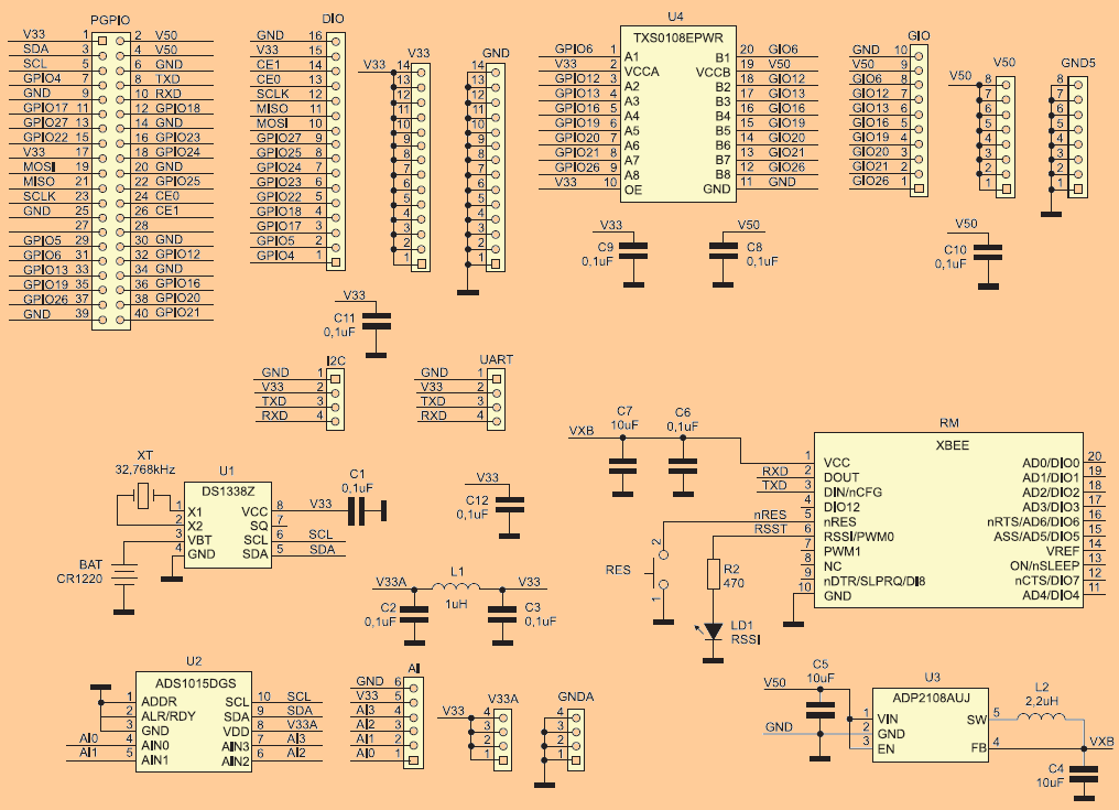
The last element of the module is the connector for Xbee compatible communication modules. Due to the different requirements for serial communication standards, compared to the RaspbPI_Com communication module for Raspberry Pi A / B, I gave up placing all interface systems on the module board.
It always turns out that part is unused or worse – there is a lack of some standard. In the next article, there will be several types of Xbee compatible modules that allow different ways of serial communication. Such a division makes it possible to use them also to work with PC, Launchpad, Arduino and all prototype platforms having an Xbee connector or expansion module.
In addition to UART signals, the RES (reset) button and the LD1 LED indicating the level of the received RSSI signal (for radio modules) are connected to the Xbee terminals. Due to the considerable current drawn by Xbee, I used a separate 3.3 V power supply with the ADP2108 chip.
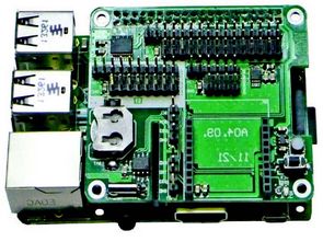
The arrangement of components on the circuit board is shown in Figure 2. It is mechanically compatible with Raspberry B + to allow the use of display and camera connectors. Four fastening holes provide mechanical stability. Installation requires no comment.
To avoid mistakes, the area with 5 V-compatible signals is highlighted with a soldermask. Please note that connecting signals exceeding 3.3V to the other GPIO Raspberry Pi pins will irreversibly damage them. Due to the sharing of UART and I²S serial interface signals by the Xbee module, UART and I²C connectors, pay attention not to use them simultaneously.
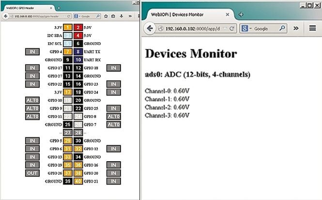
The module requires no startup. You only need to configure the system to support individual peripherals. To use RTC, it is necessary to add I²C bus support. To this end, we check if the definition of i2c-dev is in the sudo nano / etc / modules file. If not, we must add it, save the changes and restart PI. After starting, download the tools responsible for I²C support:
![]()
FILE DOWNLOAD LINK LIST (in TXT format): LINKS-26308.zip
Module d’extension Raspberry Pi
Module d’extension GPIO Raspberry Pi GPIO Pi B + La conception du module d’extension décrit permet l’utilisation de Raspberry Pi + dans les applications de contrôle et de contrôle, donnant accès à tous les signaux GPIO disponibles dans la nouvelle version.
14 × GPIO avec niveau logique CMOS 3,3 V
8 × GPIO avec convertisseur de niveau au standard CMOS 5 V.
Connecteurs UART, I²C.
Horloge en temps réel avec batterie de secours DS1338.
4 entrées analogiques avec résolution 12 bits.
Connecteur pour modules de communication compatible en termes de broches avec Xbee.
Alimentation à découpage 3,3 V pour modules Xbee.
Tous les connecteurs sont conformes à la norme Arduino Bricks, qui permet l’utilisation directe d’une large gamme de capteurs, transducteurs et actionneurs. Les signaux dans la norme 3,3 V du connecteur GPIO sont connectés au connecteur DIO et, avec les connecteurs V33 et GND, constituent un bloc compatible avec les briques Arduino 3,3 V. Le connecteur DIO a une alimentation dupliquée sur les bornes 15 et 16, ce qui facilite la signaux de sortie avec l’alimentation de bande SIP16. Cette convention s’applique à tous les connecteurs GPIO.