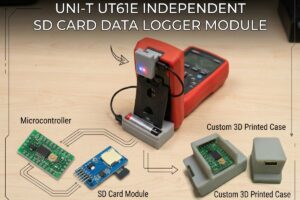
The UNI-T UT61E multimeter has the ability to connect to a computer through an RS-232-based interface, transfer measurement data to the screen, and record it. However, with this method, a computer or laptop must be kept turned on for the recording process. This is not practical for long-term measurements or portable use. In the original project, to solve this problem, a standalone logger was designed that can be powered by a power bank and write measurement data directly to an SD card.
Data transfer is carried out through the infrared LED on the multimeter and the photodetector in the interface cable, meaning that galvanic isolation is preserved.
Thanks to this solution, voltage and current measurements made with the UNI-T UT61E can be recorded in CSV format without needing a computer.
The project consists of three main sections: the first section describes the converter part that adapts the multimeter’s infrared output to a converter with a USB Type-C connection, the second section describes the logger hardware using a microSD card, and the third section describes the software that manages the recording logic.
The original content also states that a custom enclosure prepared with 3D printing is used.
1) Converter section
Contents
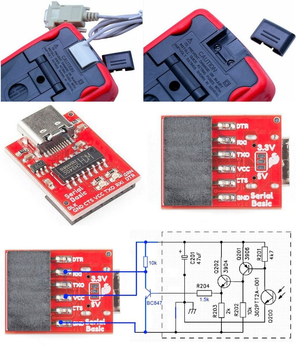
The standard cable of the UNI-T UT61E is provided with an infrared receiver and RS-232 output structure. This cable is not very practical for direct use with current computers; most of the time, an additional USB converter is required.
For this reason, a more modern and portable connection was obtained in the project by using a low-cost UART board with CH340 control and Type-C output.
On the CH340 board used, the path going to the 3.3V line was cut and bridged to the 5V side; then some component changes were made on the original IR receiver circuit.
A bridge was applied instead of the C202 capacitor in the original circuit, the R204 resistor was replaced with 1.5 kΩ, and an NPN SMD transistor similar to BC847 and a 10 kΩ resistor were additionally added. Thus, the IR receiver circuit was made compatible with the CH340-based UART converter.
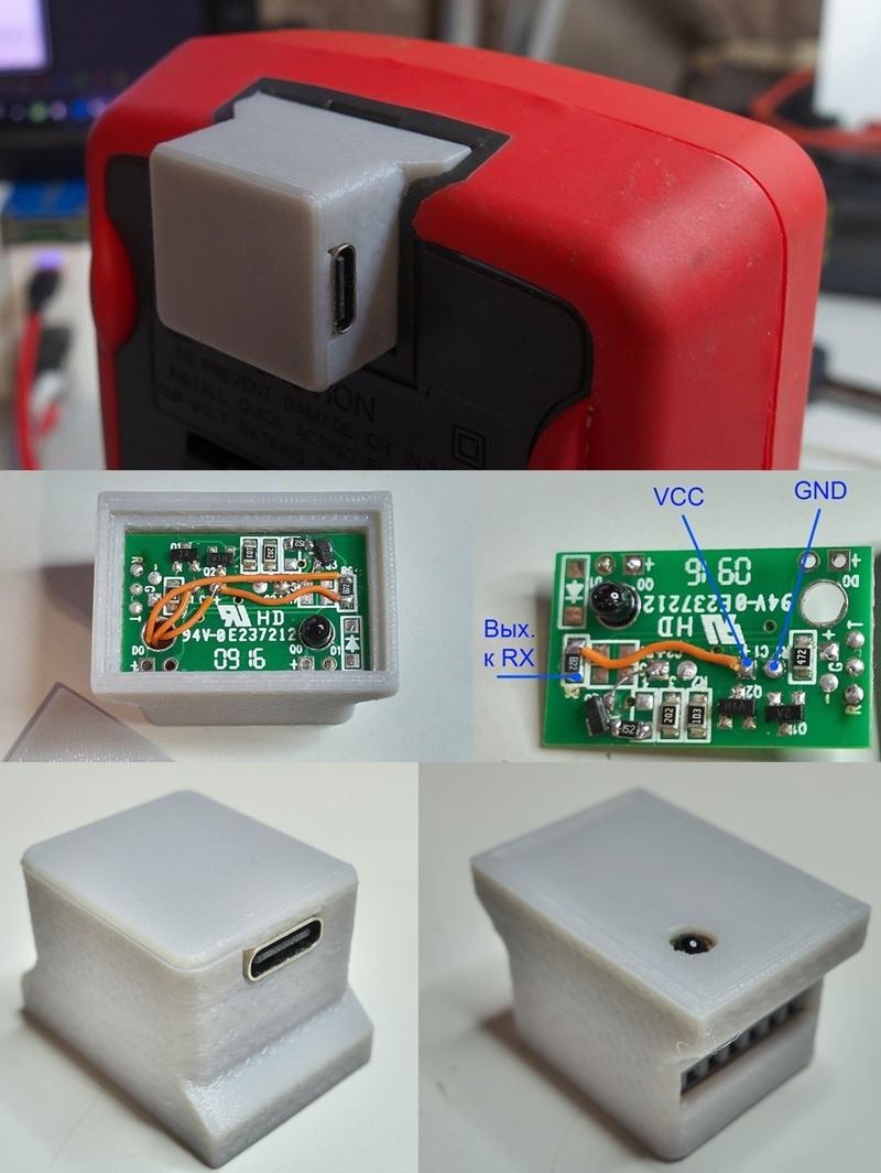
If desired, this converted IR receiver can be placed back into the original housing; alternatively, a separate 3D printed enclosure can be prepared for the two boards.
In the design prepared by the project owner, the IR receiver is positioned on one side and the UART board on the other side. Fixing was also made inside the enclosure so that the Type-C socket would not be mechanically stressed.
At the end of this first stage, when the device is connected to the multimeter, a more compact and up-to-date interface that can successfully transmit measurement data to the computer is obtained.
2) Logger hardware
On the standalone recording device side, two basic modules were used: an Arduino Pro Mini class board and a microSD card adapter.
The original project also states that the small-sized LGT8F328P-SSOP20 board was used successfully.
A custom body was again designed for the logger; the enclosure was prepared in two parts to reduce the need for support during 3D printing.
This approach was preferred because cleaning supports is difficult when printing with PET-G.
A classic SPI connection was used between the Arduino and the SD card module. The lines are given as follows: MOSI = D11, MISO = D12, SCK = D13, and CS = D9. Since the CS pin can be changed in the code, a different pin can also be assigned if needed.
It is also stated that a small physical adjustment may be required at the support point inside the enclosure depending on the length of the development board used.
After the firmware is uploaded, the hardware is tested, and if it works without problems, the body is closed and the device is finalized.
Thanks to this structure, the data coming from the multimeter is transferred directly to the logger board and written from there to the SD card. Thus, it becomes possible to collect data in the field or during long-term tests without a computer.
3) Software and operating logic

For the system to operate, a microSD or SD card with a capacity of up to 4 GB, formatted as FAT16, is required. When power is applied, the file name is created automatically; all records are kept in the same file until power is cut off.
The software records only voltage and current measurements in CSV format. Frequency, resistance, and capacitance measurements are deliberately not recorded. It is also stated that the separator character to be used between the integer and decimal parts of numbers can be set as a dot or comma.
The structure of the recording lines is time, measured value, and unit. The example format is as follows: 00:01:23;1.2345;V. The sign is preserved in positive and negative DC measurements; in AC voltage and current measurements, there is no sign. This structure makes it easier to analyze the collected data later in spreadsheet software.
Recording control is performed through the multimeter’s buttons and switch. To start recording to the SD card, the Hold function must be used twice; while Hold is active, recording is paused, and when Hold is released, recording continues.
During pause, the SD card can be removed and reinserted. Since the multimeter sends data approximately 2 times per second, the file size can increase rapidly during long-term measurements. For this reason, a sampling reduction feature has been added to the software. When the multimeter is set to the capacitance position, the recording frequency can be changed by pressing the Range button.
In the original table, it is stated that options such as approximately 2 records per second, 1 record per second, 1 every 5 seconds, 1 every 10 seconds, 1 every 30 seconds, 1 per minute, 1 every 3 minutes, and 1 every 5 minutes are offered.
The operating status can be monitored with the LED on the board. If the LED flashes at short intervals, writing to the SD card is taking place.
If the LED lights in cycles of about 2 seconds, it is understood that the card is not detected or is not inserted.
It is stated that the software was tested both on the Arduino Pro Mini and on the LGT8F328P-SSOP20 board.
Main advantages of the project
The most important advantage of this design is that it frees the UNI-T UT61E multimeter from being dependent on a computer. When powered by a power bank, the system becomes completely portable and is quite useful especially in applications that require long-term voltage or current monitoring.
Direct CSV recording to the SD card also makes later data analysis easier. In addition, since the optical data transfer structure is preserved, the galvanic isolation advantage also continues.
This type of logger can be quite functional in scenarios such as electronics hobby work, power supply tests, battery monitoring, charge-discharge curve tracking, and recording measurements at specific time intervals.
It offers a practical solution especially in cases where continuous monitoring in front of a computer is unnecessary. This conclusion is based on the recording logic and usage method described in the original project.

Source: mysku.club/blog/diy/94562.html


