The ultrasonic proximity detector circuit PIC12F675 detects the distance installed on the microcontroller as adjustable from about 30 cm to 3 m
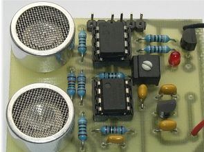
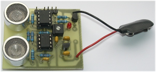
Ultrasonic Distance measurement is based on measuring the rotating time of the radiating ultrasonic wave reflected from any object. Thanks to the use of the Microchip PIC12F675 microcontroller and integrated hardware functions, the design is as simple and as small as possible, and the circuit is fitted in a PCB board.
The reflected wave connects the signal amplified with NE5532 to the input of the internal comparator (pin 6) of the PIC12F675 microcontroller.
Inside the PIC12F675 Microcontroller, an internal reference is set to the comparator and the decision level is adjusted. Changing its value (VRCON recording) makes it very easy to adjust the sensitivity of the circuit to the input signal. Thanks to the use of a high-quality operational amplifier in the IO1 position, the sensitivity is now set to the lowest possible value.
R6 is connected to the input of the internal A / D converter, which constantly monitors its current position. It is used as a decision level to measure the reflection time of the ultrasonic wave and is limited by the software in the range of about 30 cm to 3 m.
If the reflected wave is set or detected at a smaller range / distance, the microcontroller output (pin 7) and then the output transistor T1 will open, for example, control the relay, buzzer or any other system. The output is turned on by LED D1 and the output is permanently opened for the entire obstacle detection time within the set distance.
The ultrasonic sensor circuit has DIP and SMD type 2 PCB drawing. There are double-layer and single-source source asm and hex software files which are SMD.
Ultrasonic Detector circuit diagram
Source: pandatron.cz
FILE DOWNLOAD LINK LIST (in TXT format): LINKS-26627a.zip


Circuit de détection de proximité à ultrasons PIC12F675
Le circuit de détection de proximité à ultrasons PIC12F675 détecte la distance installée sur le microcontrôleur comme réglable d’environ 30 cm à 3 m
La mesure de distance ultrasonique est basée sur la mesure du temps de rotation de l’onde ultrasonique rayonnante réfléchie par n’importe quel objet. Grâce à l’utilisation du microcontrôleur Microchip PIC12F675 et des fonctions matérielles intégrées, la conception est aussi simple et aussi petite que possible, et le circuit est monté dans une carte PCB.
L’onde réfléchie relie le signal amplifié avec NE5532 à l’entrée du comparateur interne (broche 6) du microcontrôleur PIC12F675.
À l’intérieur du microcontrôleur PIC12F675, une référence interne est définie pour le comparateur et le niveau de décision est ajusté. La modification de sa valeur (enregistrement VRCON) permet d’ajuster très facilement la sensibilité du circuit au signal d’entrée. Grâce à l’utilisation d’un amplificateur opérationnel de haute qualité en position IO1, la sensibilité est désormais réglée à la valeur la plus basse possible.
The file download .zip file is password protected. The view the extracted files, it requires a password.
How might I obtain this password?
Hi,
pass: 320volt.com