Hello Friends.
In this article I will give you information about the expulsion of LED Panels with microcontroller P10.
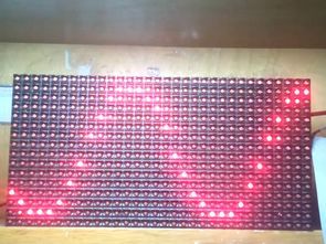
P10 LED Panels over the last few years in fashion and the market is quite a safe place. Really almost everywhere, these panels can be made using large and small graphic screens.
Normally, these panels, you can find a variety of features for driver cards. Our goal is to use this in your own custom panels, these cards can not do. I went on this point.
Anyway, I would like to point out some technical details before the details of the work. This is a business transaction to control the density of the panels, so you need to run quite high frequencies of the Panel microcontroller. That’s why I chose the work frequency and interval 18F series 2-3 or 4-panel you can manage more than increasing the speed at which these speeds, but you need to.
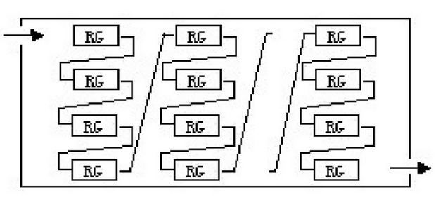
Spi Panel Communicates with. on the 16 pieces 74595 Shift Register’s profile is written in Dutch. This is how the Shift Registers as a separate section, each of the LEDs control.
the structure of the Panel like in 74595
After sending data to the Display to 74595 A and B are both pulled on the position of the OE pin 1 Display Active terminators. After a certain period of time until the data is sent to the 0 position and whether the OE PIN. Then again A and B pins are positioned and is active once again and display the position of the OE pin 1. This is the sürülüş style of the Panel.
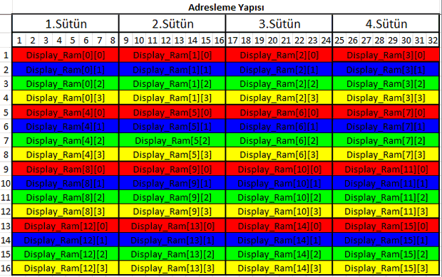
For Example; the following Table to give an example, A = 0, B = 0, only active with the renklendirdiğim Red lines in the book.
A = 1, B = 0, A = 0, B = 1, while Blue while green, A = 1, B = 1, while the Yellow Lines. Scanning and Data submission process is carried out accordingly.
With the previous data submissions in the LED Panel P10 is a little wait between sending next data is important. Increases the brightness of the Display wait too much. But all the Panel goes up in 5Ampere, close to the current. Too much of a value. Normally you have to suffer more from the current 4 Panel Amper. Otherwise, the Trailing driver enteğreler a little and get warm. This time I said, 500uS with 2000uS.
Normally, I waited for the most ideal 800uS 1000uS.
Now we know a little bit about the Panel that now we can look at the hardware and software.
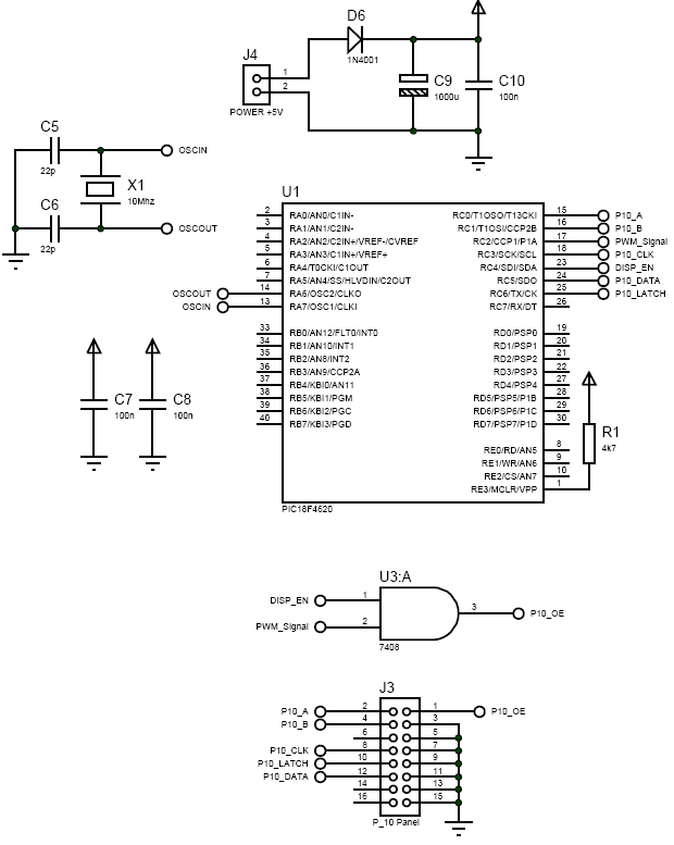
Here I used the Pic18f4620. 4xPLL interval with ran, too. In addition, by using the hardware spi module Data delivery max. I tried to reach top speed. There is more than one hardware spi and spi speed difference between oladukça.
I like the Pic with the schema, the following links between Panel.
P10 Led Panel CCS C application code:
FILE DOWNLOAD LINK LIST (in TXT format): LINKS-22075.zip


AutoCAD DWG drawings with 3D Box Designs
An estimated 2,500 box design there almost all the boxes sararım belonging to the autucad. Dwg autodesk inventor prepared with 3D drawings (. Igs,. Stp) and in PDF format dimensions, drawing information are finding a lot of PDF file size information, as well as in animation they added. “Diecast Aluminum Box, Extruded Aluminum Box, General Purpose Metal Box, Plastics Box, Diecast Aluminum Watertight Box” are awarded. In addition to being used in some box handle (Handle 3d) 3d, dwg, pdf’s in the drawing.
P10 Led-Panels mit mikrocontroller-Steuerung P10 CCS-C-Bibliothek
Hallo Freunde.
In diesem Artikel gebe ich Ihnen Informationen über die Vertreibung der LED-Panels mit mikrocontroller-P10.
P10 LED-Panels in den letzten Jahren in Mode und der Markt ist ganz sicher auf. Wirklich fast überall, diese Platten können über große und kleine Grafik-Bildschirme.
Normalerweise sind diese Platten finden Sie eine Vielzahl von features für die Fahrer-Karten. Unser Ziel ist es, dies zu nutzen, Ihre eigenen benutzerdefinierten Felder, können diese Karten nicht. Ich ging an diesem Punkt.
hello this is AjithKrishna and i am working on single color p10 board. I am trying to communicate with it using STM32F030 controller’s SPI, passed one week but didn’t found the correct procedure to light up led.s. So can you please help me out …. ! [email protected],let me know so that i can share you the code snippet. tq