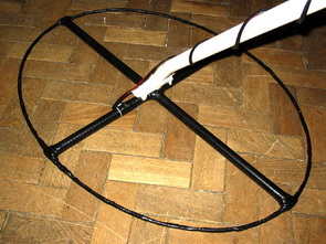
Result of displays in the form of two scales, which are estimated to judge the material goal.In addition, the screen is small scale level of response and the current supply voltage. PIC18F252 The program is intended for controller PIC18F252.The controller PIC16F873 (A) to this version can not be used. This is more demanding to resources controller. 252nd compatible controller on “pins” with 873 – m and can be programmed by the same programmer. The program workable only with korzinochnymi reels! R21 For this firmware needed zakorotit resistor R21 (in the old version of the scheme). In this version the appointment of buttons changed to read
PIC16F873A Metal Detector Clone PI
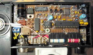
ATMega32 Metal Detector ClonePI-2
ClonePI-2 is a further development of the project ClonePI). The main objectives in the design – to get discrimination metals
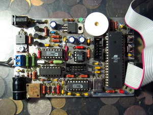
ATMega8 Metal Detector ClonePI AVR
ClonePI AVR is a so new simplistic solution pulse metal ClonePI)
# Use ATmega8 controller available from Atmel.
# Instead of using an external ADC ADC internal controller.
To get the same sensitivity as to the external ADC, is used oversampling.
# Use taktirovanie of internal RC-generator controller.
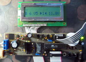
ATMega8-16PI Metal Detector ClonePI-W
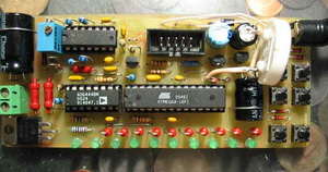
Instead of LCD used LED display. Cut down on administration, leaving only the most necessary. Take into account some errors in previous versions.
MICRICHIP, ATMEL AVR Microcontroller Controlled Metal Detector Projects all files download:
Password: 320volt.com
Published: 2008/09/23 Tags: avr project, microcontroller projects
8051 Elevator Project Stepper Motor Control
This application step (step) motor control, input and output ports through 8051 will examine the circuit by providing lift.
We use our stepper motor circuit. As we know, certain steps of the stepper motor, moving the appropriate signals are sent to the windings of a motor coach that is brought to the desired position. About this circuit about 3 ° ~ 15.3 ° with a step angle of a stepper motor is used. And our program assigns the value 10 to the tour and variable speed of about 315 ° rotation of the engine have achieved.