The Motorola 68HC908QY4 is used to produce an NTSC video signal which can be used in several applications. One is an NTSC Test Pattern Generator which produces simple test patterns in order to evaluate a TV’s geometric distortion, high voltage regulation, and interlace quality. Another is a VCR Pacifier to allow a VCR to record an audio-only signal such as from a radio. The VCR Pacifier also includes a real-time clock which is displayed either in video or by using the TV’s closed captioned decoder. Low-bandwidth data from the 68HC908QY4’s A/D inputs can be displayed the same way, turning the VCR into a two-channel data logger. As a bonus, a Video Line Trigger is presented which counts video lines from an external NTSC video source and produces a pulse to trigger an oscilloscope at the selected line(s).
Since the Horizontal rate is defined as 2/455 times the color subcarrier frequency of 3.579545 MHz. we need to start at twice the color frequency if we are going to use an integer divider.
Twice the color frequency is 7.15909 MHz. Since the QY4’s bus frequency is clock/4 we need an input clock of 7.15909 * 4 = 28.63636 MHz. (The QY4’s maximum clock is 32 MHz.)
There are two standards for NTSC video: monochrome and color. The color standard is compatible with monochrome receivers, but it almost didn’t turn out way. See NTSC Video: Background at the end of this article.
The monochrome standard calls for a horizontal rate of 15.750 KHz, a vertical rate of 60.0 Hz, and two interlaced fields of 262.5 lines to produce 525 lines per frame at 30 Hz.
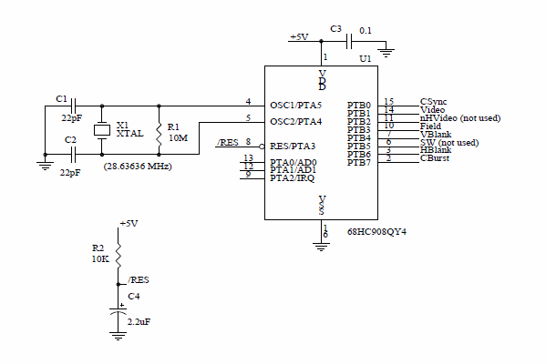
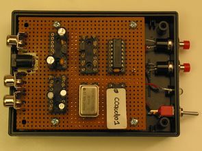
The original NTSC application required a clock of 28.63636 MHz. and used a crystal for that purpose in the standard CMOS crystal oscillator circuit shown to the right. (At this frequency R2 is not needed.)
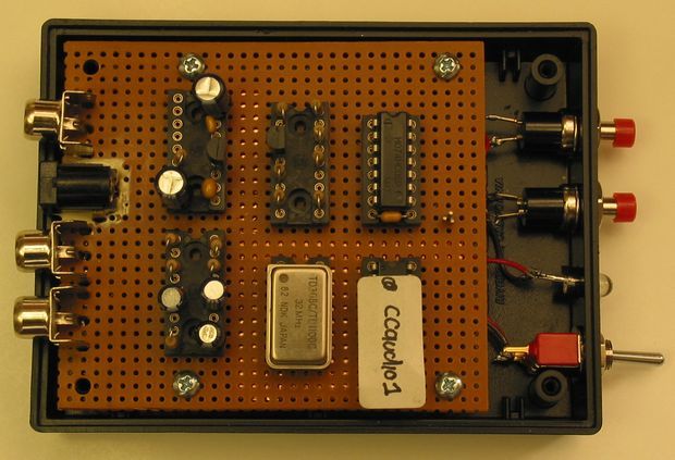
However, the applications using Closed Captioning required 32 MHz. By then, I had already built the board and did not have space to add a 32 MHz. oscillator module close to the QY4.
When I used a 32 MHz. crystal in place of the 28.63636 MHz. crystal the circuit refused to oscillate at 32 MHz. The frequency was much lower, more like 10 MHz. Author: Jed Margolin
MC68HC908QY4 NTSC Video projects files:
FILE DOWNLOAD LINK LIST (in TXT format): LINKS-21772.zip


Motorola MC68HC908QY4 MCU Remote Observation Station
Ever wonder what the birds, deer, or bear were doing in your back “40” when you weren’t around? Just set up the Remote Observation Station, and you can watch the wildlife on your TV in the comfort of your living room! The station includes a camera and transmitter that sends a picture to your TV, which can be up to a mile or two away. The station gets its power from a PV solar panel and a rechargeable battery, which rely upon the system’s control board for direction. The control board also produces battery state information, which it overlays on the picture sent to your TV. So, while you’re watching Bambi, you can also monitor the status of your battery.