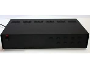
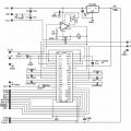
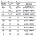
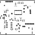
MAX5406 The proposed preamplifier is imposing several requirements. The preamp must allow volume control and balance (distribution of volume between channels), then it must allow the correction of the frequency characteristics. These requirements are satisfied by a number of integrated circuits intended for realization of the lna. These circuits, in all cases using to control the potentiometers. For the realization was chosen the circuit allows more elegant control with the buttons. This circuit is audioprocesor company Maxim MAX5406
Digital Preamplifier Circuit MAX5406
Circuit MAX5406 is audioprocesorem controlled using the buttons. Has 32 stepper potentiometer for volume management, allows the correction of low and high frequencies (lows and highs) in 21 steps, contains the function of the mute (muting the volume) and “ambience” (special effect editing sound outside-vented). The circuit is manufactured in two types of cases with 48 pins. This is the case 48 TSSOP and 48 TQFN-cases are designed for surface mounting. To implement it selected case 48 TSSOP. Audioprocesor allows connection of a symmetric or asymmetric signal. The circuit is equipped with inputs for connection of two stereo signals, which are to be aggregated. Output the signal is in the form of asymmetric stereo signal. There is also output for active subwoofer, whose signal is not úrovňově influenced by, is the only frequency limited
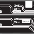
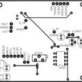
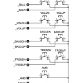
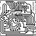
![]() max5406 circuit pcb schematic all files alternative links:
max5406 circuit pcb schematic all files alternative links:
FILE DOWNLOAD LINK LIST (in TXT format): LINKS-25504.zip
Published: 2016/06/05 Tags: audio control circuits
TDA7293 Guitar Combo Amplifier Projects
The design and construction of combos for electric guitar. Work discusses how theories of construction and design blocks combos, so its structure and measuring its parameters and parameters of individual blocks. Bachelor thesis has the aim to get acquainted with the problems of the design of individual parts of the combos, which are the preamp with a proofreader and an end-amplifier implemented as an integrated amplifier circuit TDA7293V. This solution was chosen due to its price availability, simplicity and parameters, which amplifier despite this simplicity reaches.
MAX5406 Audio-Prozessor-Vorverstärker-Projekte
MAX5406 Die vorgeschlagene Vorverstärker ist imposant mehrere Anforderungen. Der preamp muss ermöglichen, Lautstärke-Kontrolle und balance (Verteilung der Lautstärke zwischen den Kanälen), dann muss es ermöglichen die Korrektur der Frequenz-Charakteristik. Diese Anforderungen werden erfüllt durch eine Reihe von integrierten schaltungen vorgesehen, für die Realisierung der lna. Diese schaltungen, die in allen Fällen durch die Steuerung der potentiometer. Für die Realisierung wurde gewählt, die Schaltung ermöglicht es, mehr elegante Steuerung mit den Tasten. Diese Schaltung ist audioprocesor Firma Maxim MAX5406