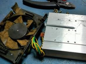
The circuit is primarily designed to monitor, control, and protect the temperature of a power supply’s cooler. It can also be used in amplifiers and other cooler-equipped circuits. It can monitor the temperature of two separate coolers. The circuit provides temperature-dependent control of a PC fan and an approximate display of the temperature using several LEDs. Optionally, if the temperature exceeds the maximum value despite fan cooling, it can activate a relay that can be used to activate certain protective functions.
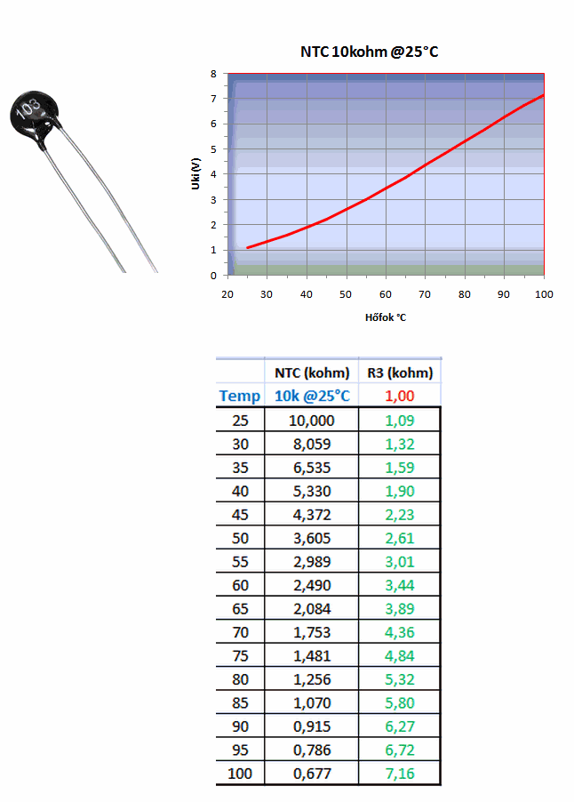
The protection relay is not built into the PCB; you can use it by connecting the relay. A 10K NTC is used for temperature measurement. The nominal resistance of the NTC is given at 25°C.
Temperature-Resistance Values of a 10K NTC
The Tmax temperature value will be determined by the Ref-Hi voltage value, which is the sum of the voltages across resistors R6 and P1, i.e., the Ref-Out voltage value.
As we know, there is a voltage drop of 1.25V across resistor R6. If P1 is short-circuited (no voltage can drop across it), the Ref-Out (minimum) voltage value will be 1.25V. If P1 is wound to its maximum, the voltage drop across U P1 is determined by I ref * P1. The I ref value is 0.668mA (because the ADJ current also flows through the P1 trimmer). Therefore, the voltage drop across P1 U P1 = I ref * P1 = 0.668mA * 10kΩ = 6.68V. Furthermore, there is a voltage drop of 1.25V across 2.2kΩ. Therefore, the Ref-Out (maximum value) can be 7.93V.
The NTC table indicates the temperature at which the Tmax value can be adjusted. The range between 30 and 60°C is approximately 1.3 to 3.5V, so it can be seen that the Tmax value can be adjusted over a wide temperature range. This voltage can be measured at pin 6 of the LM3914 and converted to temperature using the table.
The Tmin temperature value will be determined by the Ref-Lo set voltage. IC1 has 10 1kOhm resistors between the Ref-Hi and Ref-Lo pins, for a total value of 10kOhm (see datasheet). The “Tmin” adjustment potentiometer P2 is located between the Ref-Lo and GND pins. If potentiometer P2 is shorted, the entire reference voltage drops to the internal divider. That is, Ref-Out = Ref-Hi and Ref-Lo = 0V. When P2 is at its maximum position, the Ref-Out voltage is divided between the internal divider and resistor P2. So at the maximum position of P2, the value will be Ref-Lo=Ref-Out/2, that is, if we set the Ref-Out voltage to 5.3V (80°C), Ref-Lo can be adjusted between 0..2.65V (0..50°C), this value can be controlled from pin 4 of LM3914.
Temperature Display
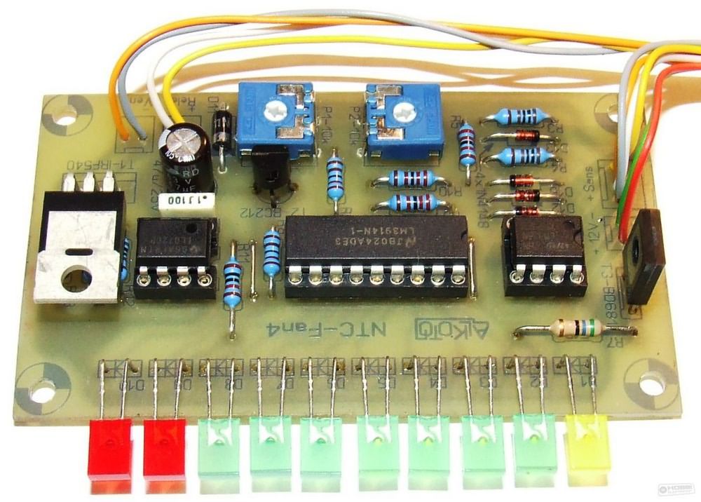
The LM3914 LED driver integrated circuit (IC) was used, assuming the fan speed and temperature are set to the voltage range Tmin – Tmax (temperature). The LM3914 can switch ten LEDs in linear steps depending on the input voltage if the input voltage is between Ref Lo and Ref Hi.
The temperature display divides the Tmin/Tmax temperature range into 10 discrete points. (More accurately, 9+1 points, since the 10th LED will activate the protection relay.) Regulation will not be a continuous, monotonically increasing function, but the fan voltage will also consist of 10 points between 4 and 12V.
Since an “initial voltage” of approximately 4V must be provided immediately upon the first LED being turned on for the fan to operate, the BD681 Darlington transistor is used as a “voltage level shifter” circuit. This essentially acts as a “high-current” Zener diode. When LED1 is turned on, the 1.2V voltage of the two series bases appears on the BD681 Darlington transistor, and as the current increases (when the LEDs are turned on in series), the voltage drop across the transistor no longer increases. The sum of the voltages across the shunt resistor and the Darlington will be the control signal for the DAC control amplifier stage. All we need to do now is increase this DAC voltage change to the 4.12V range for the fan.
Note: The DAC voltage, the input signal of the control amplifier stage, is always measured relative to +12V, not GND, just as the voltage to the fan is interpreted relative to this point!
Protection Relay
The operation of this stage in the circuit is only optional; when the temperature Tmax is reached, LED 10 indicates this. The voltage across the LED diode opens transistor T2, thus activating the relay. To ensure proper relay switching, the two feedback resistors (R9/R10) in the circuit provide hysteresis. Thanks to the D12/D13 diode, hysteresis does not affect the Tmax response point, only the feedback level.
If we do not want to support the circuit with a relay, but simply want to pass the Tmax thermal protection signal to another circuit, it is recommended to replace the relay protection diode with a 1kOhm resistor. This will result in a 0/12V logic signal at the relay output. The signal level is high when the protection is activated.
If the protection relay is not used, we do not need to install components R8, R9, R10, D11, D12, D13, and T2.
Circuit Diagram LM3914 NTC-FAN Relay

Source: hobbielektronika.hu/cikkek/hutoborda_homerseklet_szabalyozasa_es_kijelzese.html