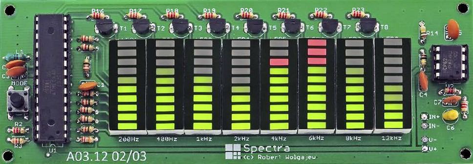
Spectrum analyzer 8 channels (200Hz, 400Hz, 1kHz, 2kHz, 4kHz, 6kHz, 8kHz, 12kHz) 10 bargraph LED display is used. Audio Spectrum analyzer device is based on Atmel ATmega48 Microcontroller. It is an advanced, more material-intensive version of the previously shared 10 Channel 100 LED Audio Spectrum Analyzer project. Since ATmega48 internal oscillator is used, crystal oscillator is not required.
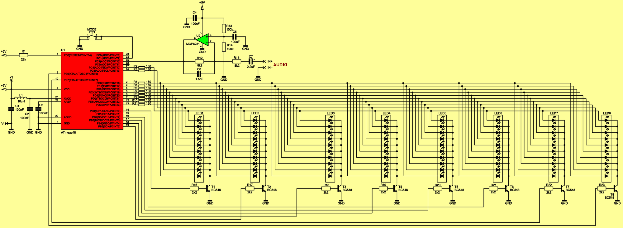
Microchip ATmega48’s main task is to sample the audio signal given to ADC2 PC2 pin, which is realized by using an internal ADC converter operating in 8-bit mode; this converter is powered by 1MHz clock signal which provides a reasonably short signal processing time (approximately 15.5µs).
Short conversion time is due to the relatively high sampling rate of the input audio signal, 25600 samples per second. This results in the desired bandwidth of the processed signal, which in this case will be 12.8 kHz.
However, before the audio signal reaches the input of the ADC converter built into the microcontroller structure, it is filtered in a simple first-order low-pass filter circuit with a cut-off frequency of approximately 12.8 kHz, created using the MCP6231 op amp integrated circuit and passive components. The gain in the filter circuit is set to 1.
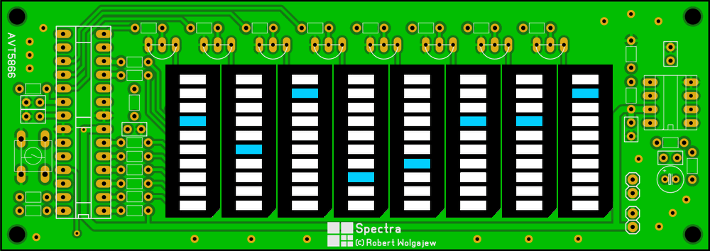
Audio Spectrum Analyzer Modes
BAR MOD
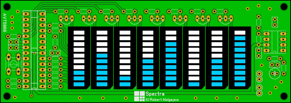
BAR NEGATIVE MOD
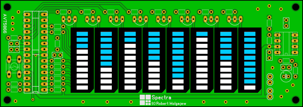
BASELINE MOD
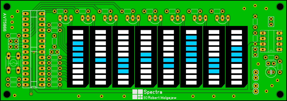
PEAK HOLD MOD
POINT MOD
Audio Spectrum Analyzer Circuit Diagram
Audio Spectrum Analyzer Basic Parameters:
Power supply: 5 VDC, approximately 170 mA
Analog input signal maximum amplitude: 2.5 V (5 Vpp)
Analyzed frequency bands: 200 Hz, 400 Hz, 1 kHz, 2 kHz, 4 kHz, 6 kHz, 8 kHz, 12 kHz
Operating Modes: 5 Units, Peak hold, Bar, Inverse bar, Point, Base line
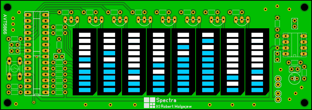
You can use bargraph LED single color or multi-color. Multi-color 10-bargraph LEDs are generally 2, 3 and 4 colors. Green and red two-color LED Bargraph was used in the project
PCB drawing was copied from the drawing in the PDF file with Sprint Layout 6 program, not checked, not tested. Check the PCB drawing according to the circuit diagram before printing the PCB. Since the PCB is two-layered, it is easier to close the lower and upper layers during the control. If you report PCB errors, I will correct them.
Source: ep.com.pl/projekty/projekty-ep/14871-spectra-analizator-widma-sygnalu-audio