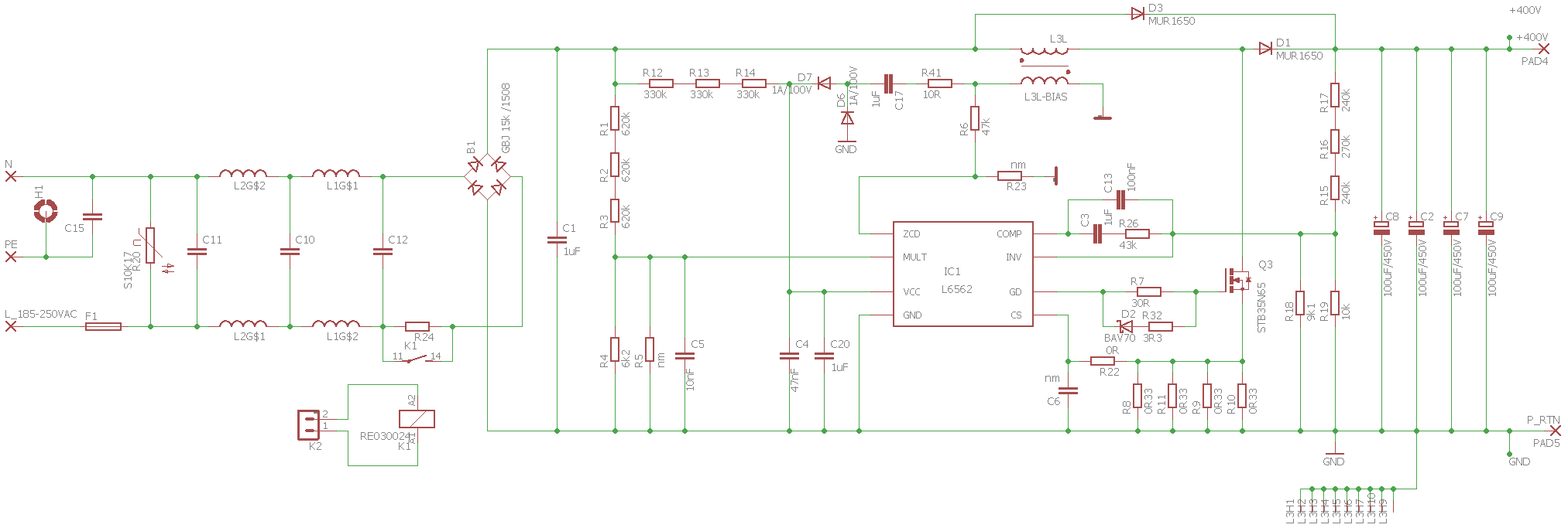
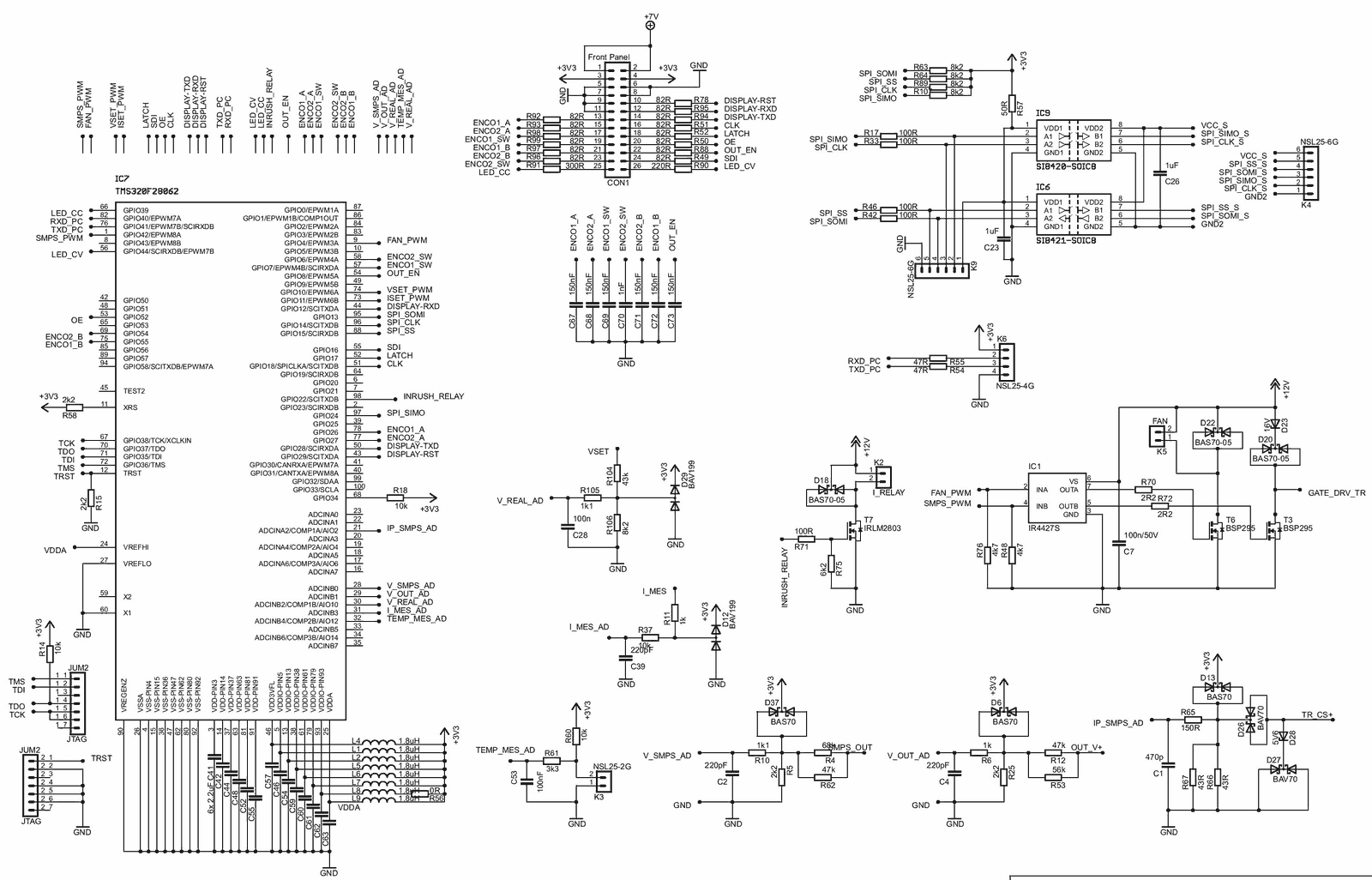
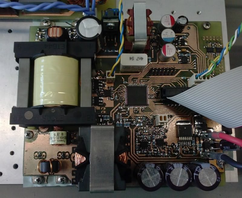
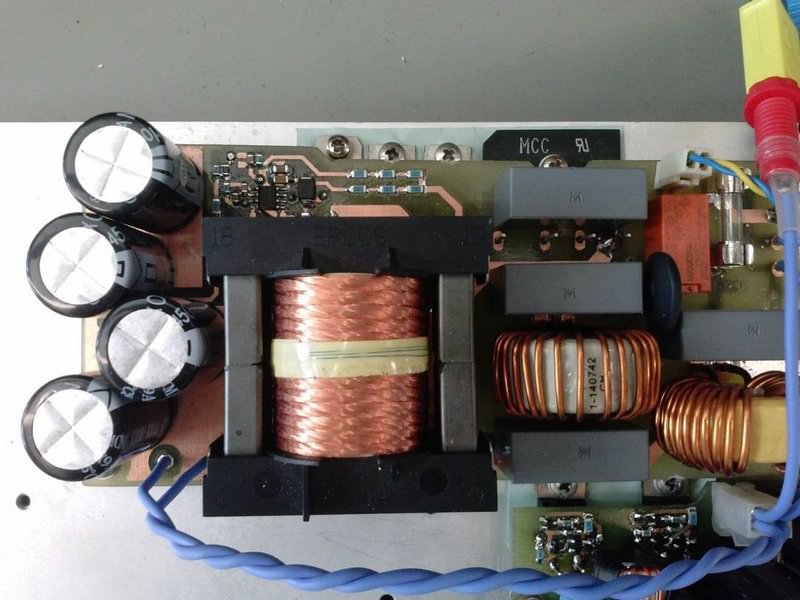
Smps circuit controlled by TMS320F28062 IR4427 Gate driver. Designed with pfc circuit L6562 The design of printed circuit boards and the creation of electrical schemes is realized through Eagle cad. Due to the design of the resulting device, the inlet filter is together with an active rectifier placed on a separate printed circuit board. On the DC DC source output modules are also located on separate circuit boards converter, TOP243 auxiliary power supply and their control circuits.
The smps coil design is considered on the ETD44 ferrite core made of 3C90 from FERROXCUBE. The core size of the coil was chosen according to the calculations for several ferrite cores with different dimensions (ETD34, ETD39, ETD44). The core ETD44 was based thus, the theoretical filling of the skeleton window by winding below 50% will give the given winding with the number of turns can be made without any problems.
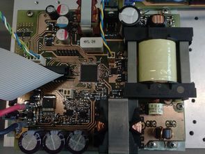
Both boards are attached to rear panel, which is also a cooler for power components. Printed circuit board user peripherals are mounted on the front panel and connected to control circuits individual modules. When designing a printed circuit, it is necessary to keep the insulation distance from the point of view of safety between the primary and secondary sides, as well as the working isolation distances between individual wires and components.
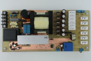
The width of the printed circuit boards must match the current will go through them. When passing a path from one printed circuit board to another, it is at The use of a number of precursors whose maximum permissible current rating is appropriate density is indicated by the printed circuit board manufacturer. It is critical in terms of electromagnetic compatibility minimizing current loops through which pulse currents flow (e.g., secondary currents) single acting forward converter rectifier).
Minimizing signal-leading loops it is equally important to the control elements because of the risk of inducing disturbing voltages and subsequent operation of the device. It is also possible to eliminate loop sizes by reducing the overall size of the device by using SMD (surface mount) components devices, i. surface mount parts), resulting in lower cost and faster PCB production. Wiring diagrams, printed circuit design together with list of components are included in the appendix.
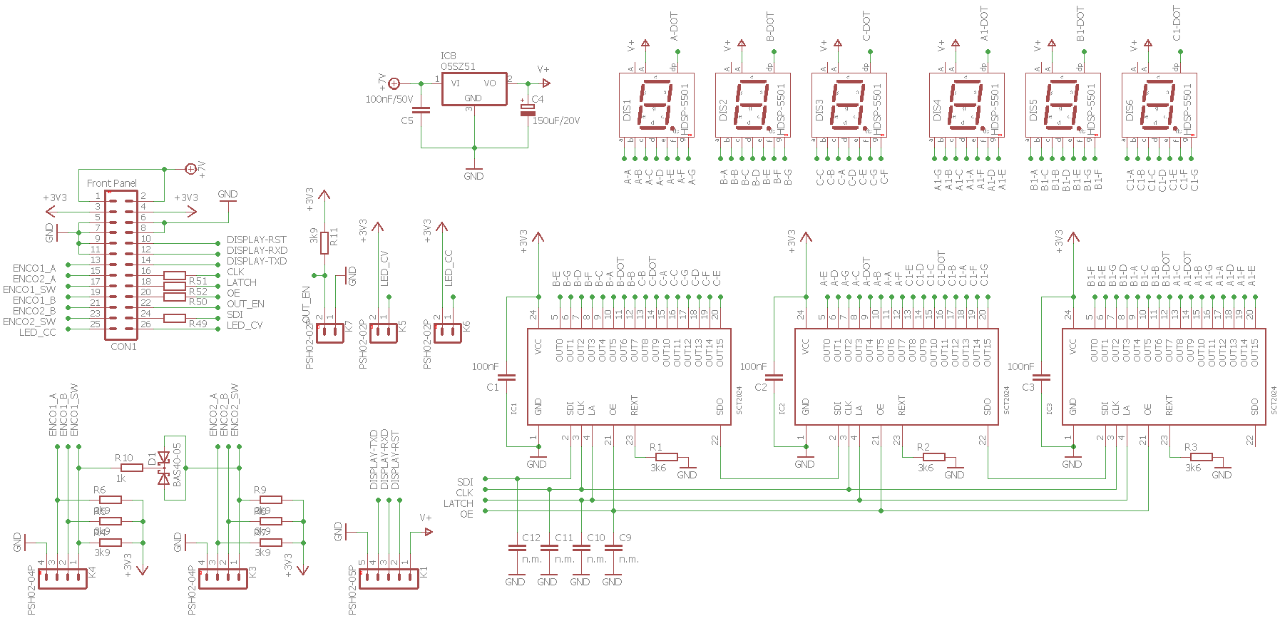
TMS320F28062 SMPS Laboratory Power Supply Schematics

![]()
FILE DOWNLOAD LINK LIST (in TXT format): LINKS-26201.zip


Alimentation d’énergie de laboratoire 10A 2X40V L6562 PFC TMS320F28062 SMPS
Circuit Smps contrôlé par le pilote de porte TMS320F28062 IR4427. Conçu avec le circuit de pfc L6562 La conception des cartes de circuits imprimés et la création de schémas électriques est réalisée par Eagle cad. En raison de la conception du dispositif résultant, le filtre d’entrée est associé à un redresseur actif placé sur une carte de circuit imprimé séparée. Sur la source DC DC, les modules de sortie sont également situés sur un convertisseur de cartes de circuits séparés, une alimentation auxiliaire TOP243 et leurs circuits de commande.