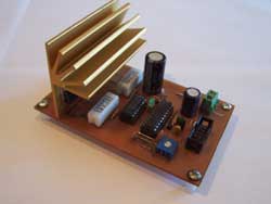
This is a Unipolar Driver controlled flow until 4A 35V, allows us to control engines 5, 6 or 8 wires in unipolar configuration. Al igual que en el driver bipolar de 2A se As in the driver bipolar 2A uses the integrated L297 which interprets the signals from the interface and controls Mosfet IRLZ24N that have been used in the phase of power. To use the current control that integrates the L297 is necessary to add some NAND gates between the signals coming out of the L297 and the gates of skunks, thereby increasing the PWM signal that regulates the flow provided by the L297 to interference from the gates Nanda interrupt the signals that go to each mosfet generating asíi the choping in the coils of the engine
L297 Mosfet Motor driver circuit 4Amp


L298 L297 Motor driver circuit 2Amp
The circuit is a Bipolar driver with current control up to 2A. It mainly consists of two integrated systems, L297 and L298. L298 contains two integrated H-bridges necessary to control the two coils of a bipolar motor, L297 is responsible for controlling these H-bridges in addition to the signals from the interface (step, address enable, etc.).
The only details to consider are the resistors R7 R8 R9 R10 which should be 1 ohm and 2Watts of power. by means of which the current flowing through each bridge is measured to control the current. The L298 must be mounted on a suitable heatsink.
There are 3 connectors for the driver connections, one for connecting the 10′ flat cable driver with the interface, the other for welding with the voltage to be applied to the motors and finally there are 4 connectors where the two motor coils are connected.
As it is a current controlled driver, higher voltages than the motor coils rated can be used, precisely current control, because using higher voltages greatly improves the performance of stepper motors, in which case you can use a source up to 42 Vdc
Current Control: Detects current through shunt resistors (R7 to R10) and provides protection to a user-set reference voltage
To regulate the current we want the driver to run, simply calculate the reference voltage according to the following perfume:
Vref = 0.5 x Motor current
After that, we have to adjust the Vref to the calculated value, for this we measure the reference voltage with a multimeter and adjust the preset (R2) until we get the desired value, we have to measure this voltage between the marked pin and gnd to measure it with the multimeter.

Source: esteca55.com.ar L298 Motor Driver Circuit schematic pcb and L297 Motor Driver Circuit pcb schematic 2 alternative link:

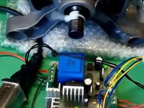

AT89S52 8051 RF DC Motor Speed Control
Wireless within a certain area with a control circuit for controlling the speed of DC Motor. Work, should I use to reach my goal I began to identify materials. These materials AT89S52 microcontroller, our independent auditor by the company manufactured and price is also suitable 433MHz UHF frequency band enables communication RF receiver and transmitter modules, (ATX-34 ARX-34) DC motor will L293B 4-channel push-pull driver IC circuit to feed the fixed were elements that will provide voltage LM7805 and the environment (condensers). Then these steps simulation, PCB drawings (drawings were made in Protel dxp2004) and watched the process of writing programs in Keil
RF DC Motor Speed Control AT89S52