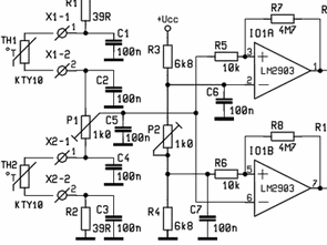
That you have seen in the diagram of the circuit feeding X3-1 and X3-2 is made from the ends. This 11-15V from input voltages entered D6, C8 and C9 by materials, a half-wave rectifier power supply for the circuit is provided. KTY10 on the circuit, there are two temperature sensors. These two sensor TH1, X1-1 and X1-2 ends, TH2-1, and the X2-X2 is linked to the second end. Supply of the two temperature sensors R1, C1, R2 and C2, C3, C4 via the resistor and capacitor can be ensured. TH1 and TH2 falling on temperature sensors, these sensors will change the internal resistance values P1 and C1, R5, low-power dual voltage comparator enters through out.

LM2903 in the structure and I01B I01 , has two low- power comparator . R3 , C6 I01 inverting input of comparator 4, R 6 , C 7 non-inverting input of the comparator is connected to I01B . I01 resistor R7 to the output of the comparator inverting , non-inverting output of the R8 resistance depends on the I01B comparators . P2 potentiometer controls these two comparator groups . If the comparator output is negative, diodes D3 and D4 of the transition is not provided , and D1 and D2 through R9 , R10 goes out to them . Meanwhile, the R12 resistor darligto transistor T1 is connected to the chassis at the end of the Beyza and darligto transmission of the transistor is not . When the positive take -out location , location is off the LEDs D1 and D2 , D3 and D4 passes current through the diode and the transistor conduction darligto T1 R11 passes out . Thus RE1 relay contacts will change position .
Caution: not shown on the schematic LM2903 op amp integrated supply legs + plus 8 numbered leg is leg number 4 – is minus the legs out of place in the scheme to VCC Please supply connection


PICKit2 Clone Circuit
PICKit2 original copy I made turned out to be different, including the PicKit2 clone shares PICKit3, but for a very long time, this design is very simple to use and also 2 version 3 .3V can be set to remove on the circuit programming with sufficient
PICKit 2 the clone belongs to a schema design, pcb layout drawings and will be installed there are hex file PK2V023200. pic18f2550 microcontroller.