Control circuit based on PIC16F88 microcontroller software prepared by the CCS-C mechanical parts used in the project, an explanation of the formulas and other related topics (english) There’s also the source CCS and MATLAB models in the Software.

DESIGN OF A TOUCH TRIGGER PROBE FOR A COORDINATE MEASURING MACHINE
Coordinate Measuring Machines (CMMs) have been widely used in industry in order to determine the form / dimensional tolerances of workpieces with very complicated geometrical shapes. Therefore, CMM is an important tool during the manufacturing and quality control phases. Workpiece to be measured on a CMM is probed via touch trigger probe through its stylus tip.
In other words, by virtue of the touch trigger probes CMM can acquire the dimensional data of the workpiece that is to be measured. Therefore the probe has become the most vital and fundamental part of the CMM. In this thesis, a novel type of touch trigger probe / scanning probe is proposed. The proposed probe can also be used as a scanning probe for different applications.
The main purpose of this thesis is to develop a novel type of touch trigger / scanning probe that has different kinematic stage and sensing stage than the other probes currently used in the industry. Giant Magnetoresistive (GMR) sensors are used for building the sensing stage of the proposed probe. GMR sensors are selected due to their outstanding sensitivity to small disturbances.
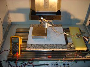
Furthermore, in order to test the proposed probe; an anvil gauge setup is designed and proposed in this study. Finally, proposed probe is tested on a three-axis computer controlled electrical discharge machine (EDM), and the results acquired from those experiments are discussed.
Hauthor: EMRE KARUÇ – Source: goo.gl/oW7f


Jet Engine Electronic Control Matlab dsPIC30F4013
A lot of work that could benefit a lot about all the details about the project, information, formulas there. Also dsPIC30F4013 prepared by the PICC C source code of software code PID control and MATLAB model, flow diagrams,’s drawing layers PCBs are circuit diagrams of the unit.
MINIATURE JET ENGINE ELECTRONIC CONTROL UNIT DESIGN
Gas turbines are widely used as power sources in many industrial and transportation applications. This kind of engine is the most preferred prime movers in aircrafts, power plants and some marine vehicles. They have different configurations according to their mechanical constructions such as turbo-prop, turbo-shaft, turbojet, etc. These engines have different efficiencies and specifications and some advantages and disadvantages compared to Otto-Cycle engines. In this thesis, a small turbojet engine is investigated in order to find different control algorithms.