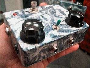
The effect circuit is based on two TL072 op amps, the VR2 100k potentiometer is used to adjust the bass sound, the circuit is powered by a 9-volt battery, since it does not consume much current, it works for a long time with a quality alkaline battery, there are layout plans, schematics, and PCB printed circuit drawings.
BASS PARALOOPER CIRCUIT DIAGRAM
A note about these sound clips. . . For comparison, each clip can be mixed with clean bass sound first, then just the effect, then the effect is mixed with clean sound from the ParaLooper. Or, maybe just the selected effect, then the effect is filled with clean sound from the ParaLooper.
ParaLooper is something that uses all the effects that use bass, because there is any sub-suction, high-pass guitar pedal out there that will ‘Bassify’. And, it’s pretty simple to build. Instead of just an effects loop pedal, this is actually a small mixer that combines your straight signal with the effects (or chain of effects) that you plug into the send and return jacks. It has wet/dry balance and overall output level (boost and cut) controls.
Experimenting with parallel effects chains is a snap, either mono or stereo. For example, you can plug the effects you plug into the send into a second amplifier or mixer/recorder channel. It can also be used just like a two-channel mixer by plugging a second source into the return jack. There is also a low-pass filter (capacitor to ground) that can be turned up for even more low end on the clean signal.
Updated 9/20/2005
I decided to redo the PCB layout for this, making it clearer and easier to follow. I also did a schematic, showing some minor component changes I made… mostly just increasing the values of some capacitors and leaving the low-pass filter for the clean signal (I never used one myself). However, the value of C5 can be selected to give the clean signal a lower end if you wish.
The pads on the layout will have a number of different sized caps in this position. I think the stock value (0.047uF) looks like a pretty natural sounding cut. However, larger values will cut the highs and pass through the lows… adjust according to the sound if necessary.
Small/simple enough to install on the chassis. However, if you want to use the toner transfer image to etch a PCB, try resizing the entire image to 2.8” x 0.9”. Then double check the pin spacing to make sure the ICs will fit before etching… adjust the dimensions if necessary.
Bass Looper Guitar Effects Sound Sample
A note about these audio clips. . . For comparison, each clip may have the clean bass sound first, then the effect only, then the effect being blended with the clean sound through the ParaLooper. Or, maybe just the chosen effect first, then the effect blensed with the clean sound through the ParaLooper.
The ParaLooper is something every effects-using Bass player should have, because it will ‘Bassify’ any bottom sucking, high-passing guitar pedal out there. And, it’s pretty simple to build, too. Instead of just an effect loop pedal, this is actually a little mixer that blends your straight signal with whatever effect (or chain of effects) you plug into the send & return jacks. There are controls for wet/dry balance and overal output level (boost & cut).
Experimenting with parallel effects chains a snap, in mono or stereo. For example, you can plug whatever effect(s) you have connected to the send into a second amplifier or mixer/recorder channel. It can also be used just like a two-channel mixer itself by plugging a second source into the return jack. There is also a low-pass filter (capacitor to ground) on the clean signal that can be switched in for even more low end.
Source: goo.gl/mwpF Guitar Effect Circuit Bass Looper alternative link:


Sound, Light indicator Heartbeat Pulse Detection Circuit
Opamp LM2904 integrated circuit based on a simple circuit that will be an example in the field of medical electronics LTM1550-01 with photo sensor heartbeat, pulse espite is done on the circuit with a buzzer sound and light warning is given with LEDs. 4 alkaline batteries can be used as a power source.
Heartbeat Pulse