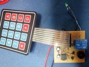
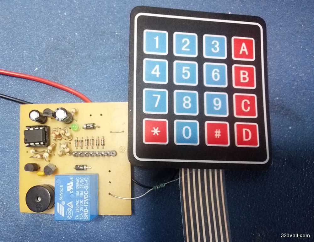
Electronic combination lock circuit or Combination door automatic LCD, LED Display etc. It is simpler and easier to implement than systems with indicators. User password can be changed with administrator password. The heart of the combination lock circuit is the PIC12F675 microcontroller. For password entry, button or old telephone keypad is used, but I designed the PCB design according to the membrane keypad.
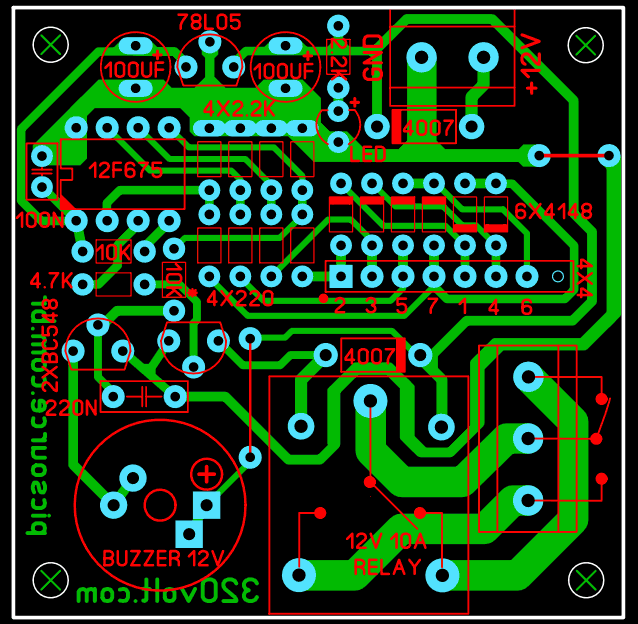
Password entry, change etc. An audible warning is given with a buzzer. The PCB design of the 6-digit combination lock circuit was prepared with Sprint layout 6, the size is 5×5 cm. I used a 1/8w resistor in the PCB drawing to keep the size small, if you don’t have it, like I did 🙂 You can place the 1/4w resistors upright.
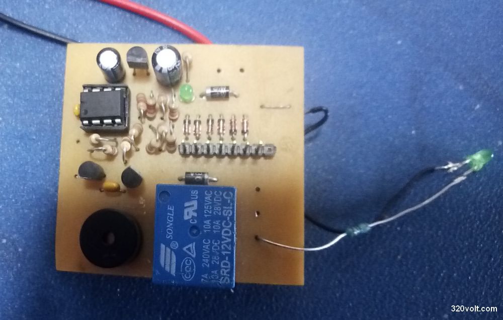
The combination lock project has source .asm and .hex code files. You can control the motor or coil to be used to open the door with a 12V 10A relay connected to the PIC12F675 output via the relay.
In the video all the information about the circuit, password operations and recompiling the .asm code with Mplab is given.
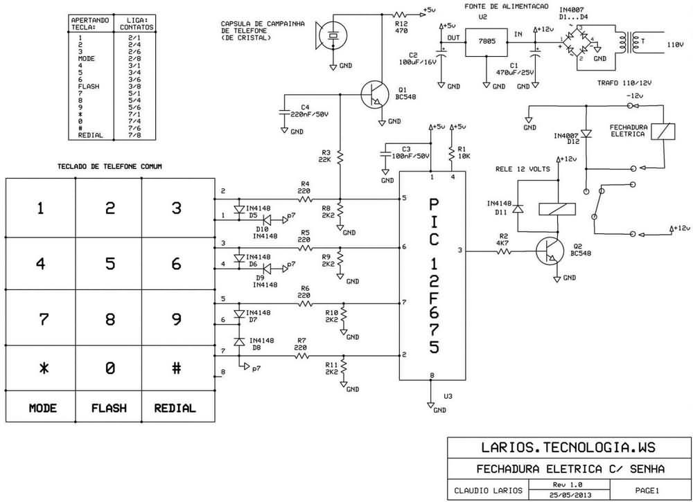
Electronic Combination Lock Schematic PCB
It can also be used as an apartment combination door lock. If you want to have a separate password for each user, you can apply the circuit in the PIC18F4620 Combination Lock for Apartment 100 User article.
PCB of the combination lock circuit, code files: 28556a.rar password: 320volt.com
Source: picsource.com.br/archives/3649


