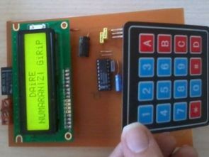
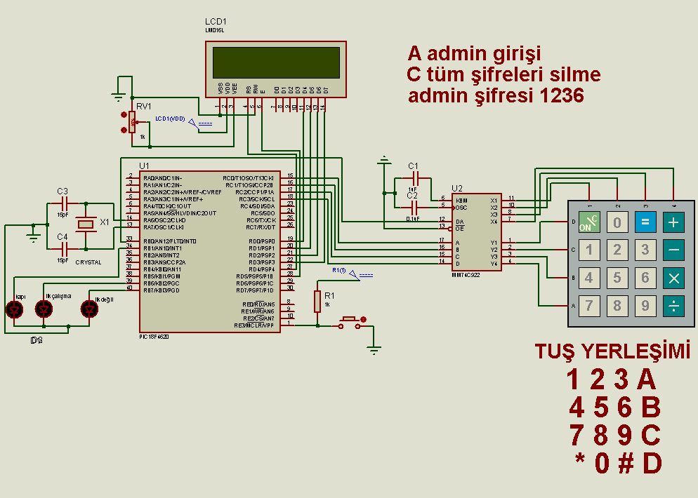
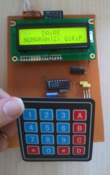
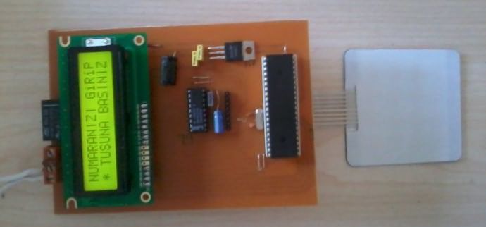
The combination lock circuit displays the information and settings entered from the keypad built on the PIC18F4620 microcontroller on the LCD screen. All user password information settings are kept in the memory of the PIC18F4620 keypad is connected to the microcontroller via the 74C922 IC.
Circuit description;
An apartment lock system where the administrator can give and delete passwords. Since all the passwords are saved in the eeprom of the PIC18F4620, the passwords are not deleted in cases such as power outages.
If the circuit is working for the first time or when it is started after all the passwords are deleted, the “first operation led” lights up, the “not first led” lights up in the next works. When the door is opened, the “door led” lights up. There are CCS C codes and proteus 7.7 simulation file and Diptrace PCB drawing.
Combination Lock Circuit Diagram
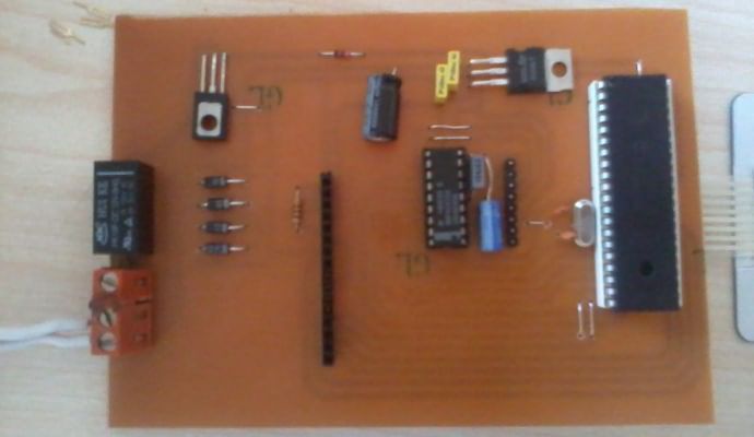
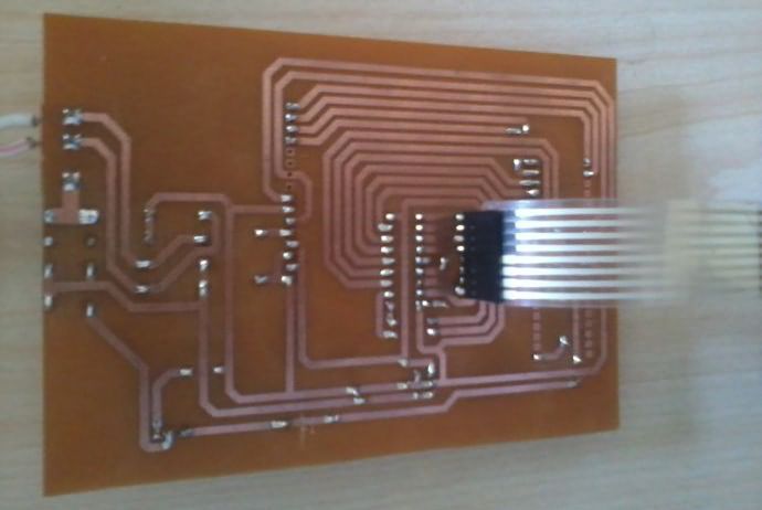
Thanks to the people who prepared the project @okanbilke.
Source: Elektroarge.com/viewtopic.php?f=107 (site down)
All files download 27371a.zip pass: 320volt.com
Publication date: 2022/10/07 Tags: microchip projects, microcontroller projects