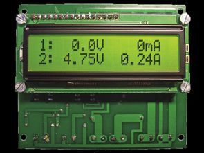
The dual channel amp volt meter circuit allows simultaneous measurement of 2 DC voltages and 2 currents on the LCD screen. Voltage measurement: 0-100 VDC or 0-10 VDC, Current measurement range 0-10A or 0-1A. The operating voltage of the circuit is between 8v-30v DC and does not require calibration.
The heart of the meter is the ATmega8 microcontroller. In the ATmega8 ADMUX register, the input number from which the measured voltage is taken is entered. It also indicates the source of the reference voltage. 2.56V internal source, external (connected to AREF pin) or voltage feeding the microcontroller. ATmega8 ADCSRA register is used to set other parameters of the converter operation,
For example: the degree of division of the system clock (for correct operation, the ADC requires clocking with a frequency in the range of 50-200 kHz), the mode of operation (continuous updating of the output data after setting the appropriate bit, the so-called Free Run Mode or conversion on demand), the method of reporting the completion of processing (an interrupt that suspends program execution or setting an appropriate flag in the register), method of data presentation (the output register has a capacity of 2×8 bits and the stored data is 10 bits; they can use the oldest or youngest bits).
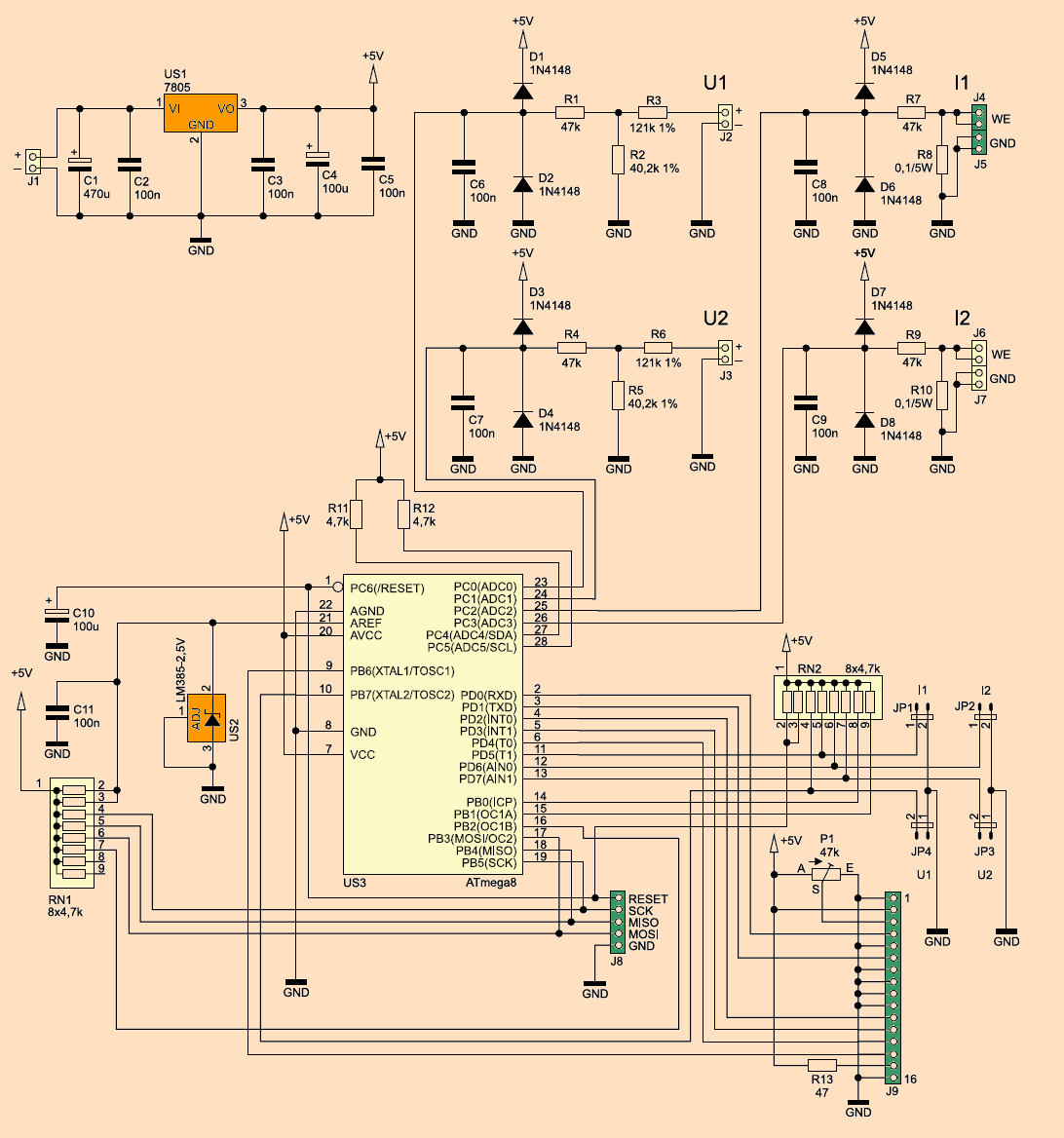
ATMEGA8 LCD Voltmeter Ammeter circuit schematic
As soon as the measurement is started, the current value of the voltage coming from the multiplexer is “locked” in the comparator. The control system manages the internal A/D converter: it feeds the second input of the comparator with half the reference voltage and checks whether it is too low or too high relative to what is measured. The bit read is recorded and plays a role in determining the next step: if the voltage is too high, subtract 1 of the reference voltage; If it is too small – add it. The second bit is read like this. The situation repeats until all 10 bits are used. Each step is a better and better approximation of the conversion result to the real value. Therefore, the largest value that can be read from a 10-bit converter is 1023:
This method of converting voltages to digital form is inexpensive and relatively easy to implement, but has a drawback characteristic of all compensating converters: it measures the voltage value instantaneously, making it unaffected by noise. This drawback is largely eliminated by the use of a dual-integration transducer that measures the average value over a period of time. However, it is a slower and much more complicated method.
The reference voltage source built into the ATmega8 Microcontroller has a very large dissipation from the nominal value of 2.56 V. These deviations reach several hundred millivolts. A calibration will be required to use. To overcome the problems, an external reference voltage source of type LM385-2.5V was used. Depending on the version, it has an accuracy of 1.5% or 3%, which is sufficient for this application. Since the circuit is connected to the circuit in the same way as the Zener diode, the current flowing through this branch is limited by two resistors connected in parallel.
A/D converter inputs are sensitive: applying voltages other than the GND … Vcc range to them is not recommended. Therefore, they are protected by a separate circuit, each consisting of two high-speed silicon diodes and a resistor that limits the current passing through them. The upper state will occur during normal operation; the middle part (the upper diode turns on) when the input voltage is too high, and the lower part (after the lower diode turns on) after applying a negative voltage to the input.
The stabilized voltage of 5 V for the microcontroller is provided by the 7805 integrated stabilizer. Therefore, the minimum value of the voltage supplying the system is 8 V. Capacitor C4, along with resistor R1, ensures that the RESET pins of the microcontroller are held low for one second after the supply voltage is applied. This significantly reduces the risk of errors during program startup, which are easy to find with increased starting voltage.
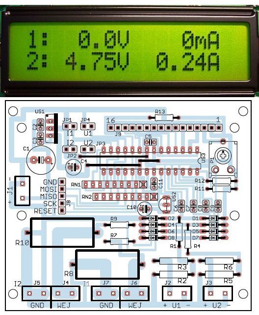
HD44780 displays to ATmega8 Microcontroller via a 2×16 character LCD screen. Potentiometer P1 is used to adjust the display contrast, and resistor R13 limits the current flowing through the backlight diodes (if the display has a backlight). The J8 connector has been added for programming the microcontroller without removing it from the socket. Fuse bits settings will not be changed, that is, they will remain at factory settings.
![]()


ATMEGA8 Das vorgestellte Gerät ermöglicht die gleichzeitige Messung von zwei Spannungen und Gleichströmen. Die Messergebnisse werden übersichtlich auf dem Flüssigkristalldisplay dargestellt. Dieses Projekt wird Entwicklern von Netzteilen, Ladegeräten und anderen Gleichstromquellen empfohlen.
Das Design geht von folgenden Annahmen aus: günstige und leicht zu beschaffende Baugruppen, Messung des Spannungsbereichs: 0… 10 VDC oder 0… 100 VDC, Strommessung von 0… 1 A oder 0… 10 A DC, Änderung des Oszilloskops ohne Beeinträchtigung der Programm im Mikrocontroller enthalten, Messungen an einem gemeinsamen Bezugspunkt, keine galvanische Trennung zwischen einzelnen Eingängen; Keine Kalibrierung erforderlich, weiter Versorgungsspannungsbereich: 8… 30 VDC, geringe Größe und unkomplizierte Montage im Gehäuse, z. B. Stromversorgung. Sofortige Arbeit nach dem Einschalten.
12V 24V 10A PWM Control Dimmer of Speed for DC Motor
12V 24V 10A PWM Control Dimmer of Speed for DC Motor
NE555 10A PWM Circuit TECHNICAL CHARACTERISTICS – Power supply: 12 to 24 VDC – Maximum output current: 10 A – Designed for low voltage motors – Adjustable frequency between 300 Hz and about 2 kHz – Current protection adjustable between 0 and 10 A – Rotation speed adjustable between 0 and 100% – MOSFET with integrated current sensor – Motor voltage: 12 to 24 Vdc – Dimensions: 15 x 8.5 x 2.5 cm.
Component technology and techniques of design are constantly changing and fixtures that we propose to you are the refl and. The speed controller for DC brush motors The subject of this article is a good example:
the component that constitutes the heart is a novelty quite remarkable. The torque regulator with the traditional PWM technology (pulse width modulation) a current limiter operating thanks to the fact that the MOSFET, to which is entrusted the impulse supply the engine, has an auxiliary terminal capable of provide a current whose intensity is proportional to that crossing the drain-source junction. A component belonging to a new class of “POWER-MOSFET” (produced by International Rectifi er) and who exactly controls itself like a traditional IRF540 or BUZ10, etc.
12V 24V 10A PWM cİRCUİT Scehematic Diagram
Hello. What is a microcode? It does not bring anything in the download.
There are download links in the zip file at the end of the article.
Hello. Yes, but nothing can be downloaded.
ist good
Can we measure Values from 2 different Power Supplies?
Buon giorno, non trovo i fuse bit, e un altra domanda, può misurare tensioni negative? Grazie.
Ciao, prova le impostazioni predefinite del fusibile
Hy please send me software code for dual volt meter i csahnge line name 1. 2. i need line 1 VGH line 2 VGL thanks .