NE555 10A PWM Circuit TECHNICAL CHARACTERISTICS – Power supply: 12 to 24 VDC – Maximum output current: 10 A – Designed for low voltage motors – Adjustable frequency between 300 Hz and about 2 kHz – Current protection adjustable between 0 and 10 A – Rotation speed adjustable between 0 and 100% – MOSFET with integrated current sensor – Motor voltage: 12 to 24 Vdc – Dimensions: 15 x 8.5 x 2.5 cm.
Component technology and techniques of design are constantly changing and fixtures that we propose to you are the refl and. The speed controller for DC brush motors The subject of this article is a good example:
the component that constitutes the heart is a novelty quite remarkable. The torque regulator with the traditional PWM technology (pulse width modulation) a current limiter operating thanks to the fact that the MOSFET, to which is entrusted the impulse supply the engine, has an auxiliary terminal capable of provide a current whose intensity is proportional to that crossing the drain-source junction. A component belonging to a new class of “POWER-MOSFET” (produced by International Rectifi er)
12V 24V 10A PWM cİRCUİT Scehematic Diagram

A U2 voltage regulator 7809 stabilizes the power supply at 9 V necessary to the circuit: indeed, this voltage feeds the PWM regulator and the current protection that, requiring reference potentials, claim good stability. Thanks to the respectable fi ltering capacity obtained with C7, C8 and C10, U2 constitutes a true wall that peaks and voltage drops due to the switching of the MOSFET on the motor armature can practically not to cross. The fuse intervenes, by cutting the power line main, when the circuit or motor tends to consume more current than the limitation does not allow it.
The heart of the PWM system is the generator realized by the coupling of a multivibrator particular astable and a comparator Operational amplifi er: indeed, to produce the pulses modulated width we compare a continuous potential to a waveform quasi-triangular produced by a spindle of U1, an NE555 mounted in astable configuration. This timer produces a rectangular wave by charging and discharging a capacitor inserted into its timing network, that is to say by letting it load through R1, D1, R2 and R23, then unloading it through R2, R3, R23 and D2, when the logical level the output is reversed. Pin 3, not used, is not on the diagram. The exponential component is taken at the terminals of C1: the comparison, devolved at the U3a operational level (confi comparator), the quasi-triangular wave (pin 2) and DC voltage routed to pin 3 by T4 and by the trimmer R24, determines at the output (pin 1) a rectangular waveform, whose cyclical report depends strictly the amplitude of the voltage due precisely at T4 and R24. Let’s see how the comparator works : its output is at the logical level high (roughly the potential of the diet positive) when the value of the component present at the terminals of C1 is lower than that applied to the pin 3 and, conversely, she gets about 0 V if the voltage almost triangular taken from the astable takes more amplitude than the potential of reference.
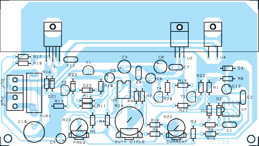
R1 .... 4.7 kΩ
R2 .... 4.7 kΩ
R3 .... 10 kΩ
R4 .... 47 kΩ
R5 .... 4.7 kΩ
R6 .... 4.7 kΩ
R7 .... 10 kΩ
R8 .... 4.7 kΩ
R9 .... 470 kΩ
R10 .. 6.8 kΩ
R11 .. 3.9 kΩ
R12 .. 3.9 kΩ
R13 .. 6.8 kΩ
R14 .. 10 kΩ
R15 .. 220 Ω
R16 .. 220 Ω
R17 .. 1 kΩ
R18 .. 220 Ω
R19 .. 10 kΩ
R20 .. 4.7 kΩ
R21 .. 10 kΩ
R22 .. 10 kΩ
R23 .. trimmer 25 kΩ
R24 .. trimmer 10 kΩ
R25 .. trimmer 1 kΩ
C1 .... 10 nF multilayer
C2 .... 10 nF polyester
C3 .... 100 μF 50 V electrolytic
C4 .... 100 nF multilayer
C5 .... 4.7 μF 63 V electrolytic
C6 .... 1 μF 100 V electrolytic
C7 .... 100 nF multilayer
C8 .... 100 μF 50 V electrolytic
C9 .... 2.2 μF 100 V electrolytic
C10 .. 1000 μF 25 V electrolytic
C11 .. 100 nF multilayer
C12 .. 10 μF 63 V electrolytic
C13 .. 1000 μF 25 V electrolytic
D1 .... 1N4148
D1 .... 1N4148
D1 .... 1N4148
DZ1 .. zener 12 V
DZ2 .. zener 3.9 V
DZ3 .. zener 3.9 V
U1 .... NE555
U2 .... L7809
U3 .... CA3240
U4 .... MBR745
T1 ..... BC557
T2 ..... BC547
T3 ..... IRC540
T4 ..... BC557
T5 ..... BC547


NE555 10A PWM-Stromkreis TECHNISCHE EIGENSCHAFTEN – Stromversorgung: 12 bis 24 VDC – Maximaler Ausgangsstrom: 10 A – Konzipiert für Niederspannungsmotoren – Einstellbare Frequenz zwischen 300 Hz und ca. 2 kHz – Stromschutz zwischen 0 und 10 A einstellbar – Drehzahl einstellbar zwischen 0 und 100% – MOSFET mit integriertem Stromsensor – Motorspannung: 12 bis 24 VDC – Abmessungen: 15 x 8,5 x 2,5 cm.
Komponententechnologie und Designtechniken ändern sich ständig und Vorrichtungen, die wir Ihnen vorschlagen, sind der Refl und. Der Drehzahlregler für DC-Bürstenmotoren Das Thema dieses Artikels ist ein gutes Beispiel:
Die Komponente, die das Herz ausmacht, ist eine bemerkenswerte Neuheit. Der Drehmomentregler mit der traditionellen PWM-Technologie (Pulsweitenmodulation) arbeitet mit einem Strombegrenzer, da der MOSFET, dem die Impulsversorgung des Motors anvertraut ist, über einen Hilfsklemmen verfügt, der einen Strom liefern kann, dessen Intensität proportional zu dieser ist Überqueren der Drain-Source-Verbindung. Eine Komponente, die zu einer neuen Klasse von „POWER-MOSFET“ (hergestellt von International Rectifier) gehört und sich genau wie ein herkömmlicher IRF540 oder BUZ10 usw. steuert.
Dual LCD Voltmeter Ammeter 0.100 VDC 0.10 A DC ATMEGA8
Dual LCD Voltmeter Ammeter 0.100 VDC 0.10 A DC ATMEGA8
ATMEGA8 The presented device allows simultaneous measurement of two voltages and DC currents. The measurement results are presented in a clear way on the liquid crystal display. This project is recommended to developers of power supplies, chargers and other DC sources.
The design assumes the following assumptions: cheap and easy to get subassemblies, Measurement of voltage range: 0 … 10 VDC or 0 … 100 VDC, current measurement from 0 … 1 A or 0 … 10 A DC, change the scope without interfering with the program included in the microcontroller, measurements using a common reference point, no galvanic isolation between individual inputs; no need to calibrate, wide supply voltage range: 8 … 30 VDC, small size and uncomplicated way of mounting in the housing, eg power supply, Immediate work after turning on the power.
ATMEGA8 LCD Voltmeter Ammeter circuit schematic