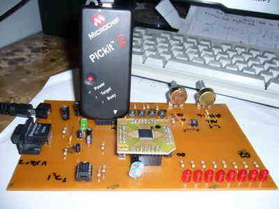
Beginner level LEDs, buttons, analog input, 24Cxx EEPROM and serial communication with the PC I did try a little experiment where you can make your own set. Wishing to be helpful. Simple DSPIC Development Board
Try this with a set of tiny LEDs, buttons, analog input, read and write 24Cxx EEPROM, serial communication with the PC experiments. PICKIT2 as programmer, I’m using dsPIC dspıc33fj256gp506 in as.
DSPIC Board

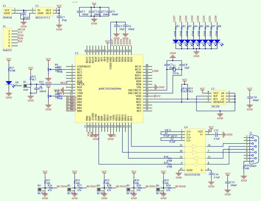
LEDs: D0 and D7 connected to
Buttons: B0 to B4 bound
Pots: AN5 and AN16 dependent
24Cxx: SCL1 and connected to sda1
Serial communication module is connected to UART2. The circuit diagram is drawn with Altium Designer 6.7
DSPIC Development Board Circuit Diagram
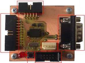
DSPIC Development Board PCB schematic files:
Simple DSPIC Experiment Development Board ZIP File Password: 320volt.com
JFET Compressor Circuit
Compressor Circuit -Ratio-Threshold-Attack and Release controls Out Level bypass feature ensures that there is a 9 volt battery works with sprint circuit layout prepared by PCBs