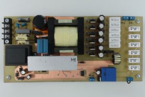
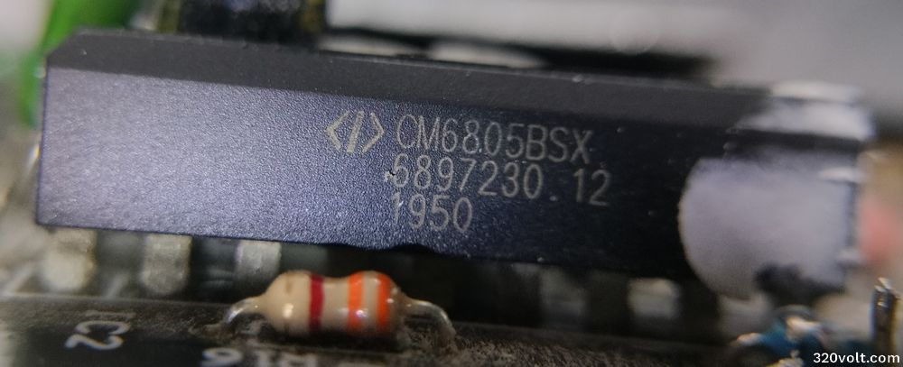
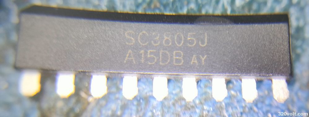
I modified the ATX 80 Plus power supply with active PFC using SC3805 or CM6805BSX integrated circuits for single output 13.8V high power. In the article “Flyback atx power supply review and modification” that I shared before, the UC3843 PWM controlled ATX power supply is controlled with optocouplers in a similar structure.
There are 3 optocouplers for control;
1: Used for standby 5V line.
2: Used for opening the power supply (PS ON).
3: Controls the system according to feedback voltage information.

SC3805, CM6805BSX series integrated circuits are offered as “Green-Mode PFC-PWM Combo Controller” which has become popular in Chinese power supplies like TL494, that is, both PFC and PWM control are combined, as I did in UC3843 ATX Power Supply, the emitter of the optocoupler used for PS-ON on-off operation and short-circuiting the collector causes the system to work unstable.
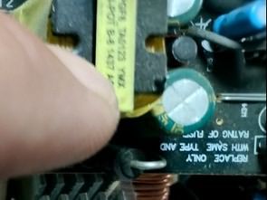
Instead, it is necessary to keep the optocoupler constantly running. It is enough to separate the path of the optocoupler’s end going to the control integrated circuit and pull it to chassis. Then we remove the existing TL431 reference resistors and install the resistors we determine according to the voltage we need. For 13.8v, I connected 15K to the 12V line and 3.3K to chassis (I need to increase the 15K value a little)
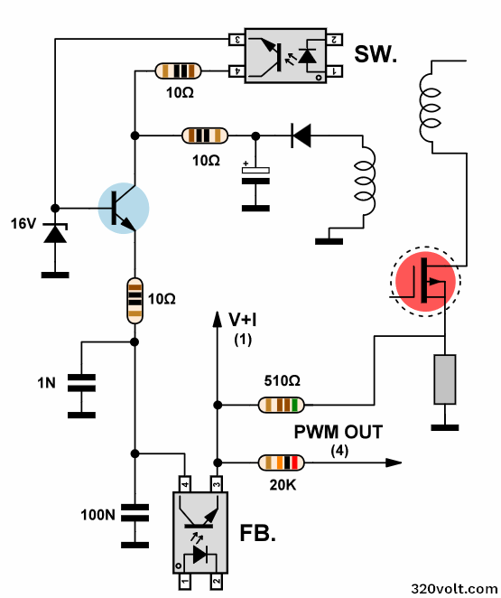
I could not find a PC power supply diagram using CM6805BSX, I am showing the process done on a similar diagram.

In the power supply I used, the LED anode of the optocoupler was connected to the standby +5V line with 1.2K, and the LED cathode went directly to the 3-channel voltage controller, GR8313 integrated circuit, so I cut that end and gave it to the chassis. In other words, depending on the brand and model, resistance values etc. may change, and the process will be as in the diagram.
According to the CM6805BS data sheets, the optocoupler used for on-off seems to have more functions.. I can use this when I switch to the current adjustment modification…
Manufacturer’s description for CM6805BS V+I;
Since the CM6805BS PWM Section is different from the CM6800 family, the emitter of the photocouple needs to be connected to V+I instead of the collector. The PWM current information also goes to V+I. Usually, the PWM current information requires an RC filter before going to V+I.
Therefore, V+I is actually a summing node from the photocouple and the voltage information from the PC817 and the current information from one end of the PWM sense resistor, and the signal passes through a single-pole RC filter and then enters the V+I pin.
This RC filter at V+I also serves several functions:
1.) Protects the CM6805BS.
2.) Provides level shifting for the voltage information.
3.) Filters out switching noise from the current information.
In normal operation, the threshold voltage of the V + I pin is 1.5 V. When V + I is greater than 1.5 V, the PWM output driver turns off the PWM Power MOSFET. When the Soft Start is triggered, the V + I threshold is about 150 mV.
PFC ATX Modified Short description and test video;
Let me talk about these new generation PFC ATX power supplies. Compared to the old ones, the power of the 5V and 3.3V outputs is low, the highest power is on the 12V line, old ATX power supplies, in the TL494 era, 5V and 3.3V would be very powerful, the transformer winding is thick, the diodes are 30 amps, etc.
Now the strongest output is 12V, and even in some PFC ATX power supplies, DC DC modules are used for the 5V 3.3V output, and the voltage input of these modules is taken from the 12V line. A long time ago Intel announced that it would only use 12V on its motherboards (ATX12VO). I don’t know if it has reached our market, but when I look at these power supplies, it seems like everything will be done with 12V in the future…
I am adding the CM6805(A-B-C)/CM6806(A-B-C), ABC0401A03A-03C-05A, ABC0401A06A-01B and CM6805BS datasheet files and the Hiper HPU4S425PU PSU diagram used in CM6805, the 19V 90W adapter diagram, the Hiper 550W PSU diagram used in CM6806AG.