Battery charging circuit is based on atmel attiny26lp, works as switched pwm, does fast charging, 100uh coil and irf5305 irl3803 mosfets are used in the switching circuit, the charging current can be adjusted between 300 mA, 600 mA … 4500 mA. A good example of power control application for people dealing with atmel series. For fast charging applications with microcontrollers, the driver in the output section is a good example in the pwm section. Also, the file you will download contains detailed theoretical information. There are all sources, eagle pcb schema, matlab, software files, etc.

The circuit is a small but very powerful charger for nickel-cadmium and nickel-metal hydride batteries. It has been developed to charge individual battery cells with high efficiency using high currents using the reflex charging process. The charging current can be specified in 15 steps using one-button operation (typically: 300 mA, 600 mA, … 4500 mA). The end of the charge is reliably detected by estimating the maximum voltage. A “-dU” detection and a timeout are also used as security. A normal charging mode (C/10) with a timeout is applied to create new batteries.
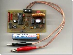
Basically, the circuit consists of Atmel’s small microcontroller ATTiny26, two powerful MOSFETs, a 470 uF electrolytic capacitor and a 100 uH coil. Current control and charging are performed by software.
In fast charge mode, the set current is used for charging. In order to reliably recognize the optimal time for charging to end, the selected current must not be less than C/2 (C denotes the current in amps (A) corresponding to the battery capacity nominally stated in ampere hours (Ah)) . When charging starts, the charging current is gradually increased to the target current. Charging takes place in the cycle shown:
T_1 : Duration of one cycle – approx. 1.02 sec
T_2 : constant current charging – approx. 1 s
T_3 : Pause between charge and discharge – about 1 ms
T_4 : Pause for measuring battery voltage and communicating with PC for example – approx. 10 ms
T_5 : Duration of a discharge pulse ramp depending on maximum discharge current, inductance used and battery voltage – typically 200 us
In current firmware, the battery is charged with three sequential discharge pulses with a peak value of four times the charge current.
NiMH NiCd Battery Fast Charger Features
Charging current up to approx. 6 A
Simple and small structure (one-sided board: 75×50 mm); no active cooling and no heat sink required
reflex charge; triple end-of-charge detection: peak estimation, -dU, max. 3 hours
Soft start in fast charge mode
Normal charge (end of charge after about 14 hours)
One button operation
30 different charging currents can be selected (15 fast charging currents and 15 normal charging currents)
Voltage/current and stopping criterion can be monitored via serial interface
Calibration test modes
Technicial Specifications:
Working Voltage: 9V.. 15V
Charging current: 0 .. 6 A
Charge voltage: 0.5 V .. 8 V (at 12 V operating voltage, max 4 NiCd cells / 5 NiMH cells)
The operating voltage source must be able to supply sufficient power for the respective charging process. For example, with a 12 V / 1 A (=12 W) plug-in power supply, a single battery cell can be charged with a maximum of 6 A at a generously estimated charge voltage of 2 V. In two cells, only 3 A is possible.
source student.uni-kl.de/~dittrich/trxcharger/index.html NiMH NiCd Battery Fast PWM Charger Circuit Atmel AVR attiny26lp alternative link:


PIC16F877 Stepper Motor Driver Circuit CCS C
stepper motor drive circuit diagram ccs c code hex “check-16F877 pic stepper-motor control can be made back and forth provided with 2 × 16 LCD 12volt driver steps on the screen you can see the details bc548 transistors used in section
CCS C Stepper Motor Driver