Pcb and schematic (sch) drawings are prepared with P-CAD 2004 Schematic V18.00.2690 and there are also test codes prepared in c language. Features of Atmega32 board:
7v – 12v power supply (4 mm sockets) with reverse polarity protection
Indication of the status of the eight logic outputs by 8 LEDs (optional depending on the wiring of the HE10 input connector: PORTA, PORTB, PORTC, PORTD or encrypted keyboard outputs)
8 inverters to create logic levels on logic inputs
2 potentiometers for generating adjustable voltages on analog inputs
4 HE10 connectors to connect ATMEGA32’s ports to keyboard, LCD display, LEDs, inverters or other boards that allow creating logic levels
1 HE10 connector for ISP connection (ATMEGA32 programming)
1 HE10 connector for JTAG connection (ATMEGA32 emulation)
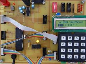
1 16-key keyboard, encoding and output on HE10 connector
1 LCD screen 2×16 characters, input on HE10 connector
1 female DB9 serial connector, for example to communicate with a PC
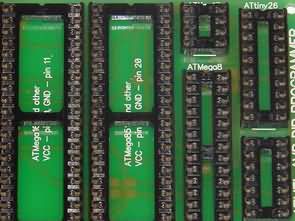
Atmel Atmega32 development board

Files:
usart.h: library “usart.lib”: associated header file.
usart.lib: “usart.lib” library containing functions that can be used with serial connection: display of chain on PC (Terater pro terminal), hexadecimal binary numbers.
lcd2x16.h: Library “lcd2x16.lib” associated header file
lcd2x16.lib: The “lcd2x16.lib” library that contains functions that can be used with an LCD display and allows numbers (decimal, hexadecimal, binary) or strings to be displayed on a 2 x 16 character LCD display.
ttpro313.zip: “Teraterm Pro” version 3.1 installation file: terminal which, among other things, allows communication via serial connection between a PC and an ATMEGA microcontroller
cvavre.zip: “CodeVision AVR C Compiler” installation file (CodeVision AVR v2.03.5, 2k limited)
test.c: Application example with CAN, keyboard, LCD screen and serial connection (source file)
test.prj: Application example with CAN, keyboard, LCD screen and serial connection (project file)
pwm.c: Application example: PWM signal generation (source file)
pwm.prj: Application example: Generating the PWM signal (project file)
devel_atmega32.PCB: development board for ATMEGA 32 (PCB in PCAD format)
devel_atmega32.SCH: Development Board (PCAD Diagram) for ATMEGA 32
centtronic.SCH: board with Centronic connector on PC side and HE10 connector on development board side, allowing programming of ATMEGA32 microcontroller (schematic in PCAD format)
centtronics.PCB: Board with Centronic connector on PC side and HE10 connector on development board side, allows programming of ATMEGA32 microcontroller (printed in PCAD format)
Source: stielec.free.fr/ Atmel Atmega32 Testing development board PCB schematic and sapmle code alternative link:
STK4192 Amplifier Circuit PCB Speaker Protection Volume Control
STK4192 Datasheet file is located in the standard application circuit according to the pcb prepared in addition to the speaker protection circuit and fan to feed the output volume to control potentiometer attached circuit supply voltage of + -35 volts DC symmetrical supply 2x25v AC (25vac x 1:41 = 35VDC) 150W power transformer enough would
STK4192 2X50 Watt Amplifier Project