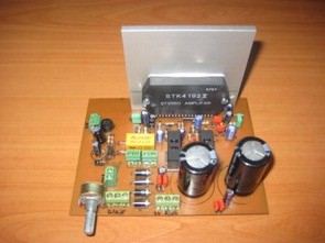
The PCB is prepared according to the standard application circuit in the STK4192 Datasheet file, the supply voltage of the circuit with a potentiometer added to control the output sound level for the speaker protection circuit and fan supply, +-35 volts dc symmetrical supply 2x25v AC (25vac x 1.41=35vdc) 150W transformer is sufficient It is possible.
STK4192 2X50 Watt Amplifier Project


The stk4192 series (STK4192II) and STK4101V series (high-grade type) are pin-compatible in the output range of 6W to 50W and enable easy design.
• Small-sized package whose pin assignment is the same as that of the STK4101II series
• Built-in muting circuit to cut off various kinds of pop noise
• Greatly reduced heat sink due to substrate temperature 125°C guaranteed
• Excellent cost performance
STK4192 2X50 Watt Amplifier proteus ares pcb files


Central Security System with pic16f877
Circuit Operation: PIC16F877 used in the circuit of the B and D as input port is selected. 8 of these units with port B doors, windows and etc.. from places logic 1 or 0 state is evaluated. D port is necessary for system operation or stopping the input of a predetermined password has been supplied. A and C are chosen as output port with port status LEDs and alarm circuit has been. C port to the B port is where you get the warning from the 7 segment LED display is used as the indicator showing. Instead of port 1 LED alarm circuit 1 or 0 is used to determine whether, enter the password warning LED LED 2, 3 the password is correct, and that LED LED LED yandıkd 4 seconds after the system is activated. 4 LED lights up when the system stops enter the password.
Security System Schematic