
RGB Led cube circuit is basically a real 3D display. Its resolution is determined by the number of LEDs. Greater resolution offers more faithful effects, but the demands on RGB LEDs and controls increase with the cube. So it is advisable to choose the right compromise, between difficulty and resolution. Here is the size of the cube 5, but the LEDs are RGB, making the effects more interesting.
ATmega64 was chosen as the control MCU, mainly because of its flash memory size (64kB). It also has a large number of pins, hardware PWM, UART, SPI and I2C interface. Because RGB LEDs are used, we get 3 color channels. PWM is used to control the light of each channel: R, G, and B. If all channels on the LED are “active”, virtually any color can be set with PWM. The limitation here is mainly in terms of software and that one PWM combination can be set for one whole 3D image.
Because the entire device was designed to be powered directly from USB without the need for an external source, a DC / DC converter was added to the design. This brings several benefits:
Less consumption
More safety
External power option
Because the supply voltage for AVR and LED is lower, it is also possible to use smaller series resistors for LEDs. Thus, there will be less losses on these resistors and the loss of power will be reduced. The DC / DC voltage of the drive has been selected to 3.9V. This voltage is large enough to light up the blue LED, and there will be enough margin for transistors and conductors. In addition, due to the lower voltage, the LED will not be damaged during polarity reversal (eg short circuit).
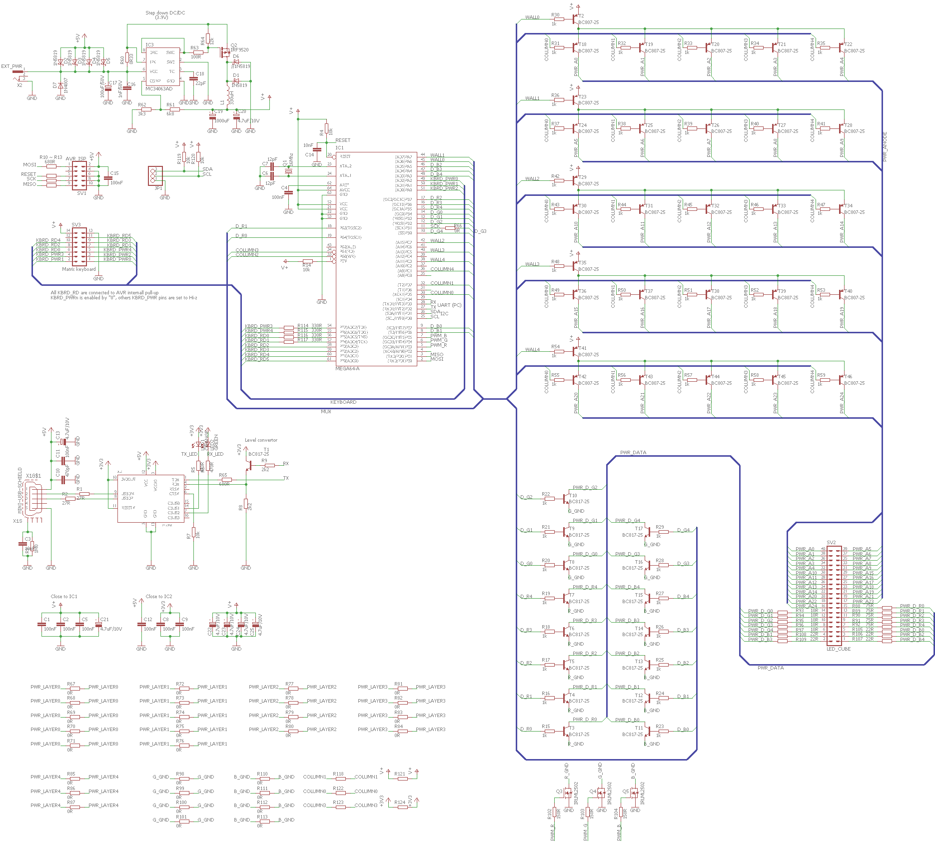
RGB LED Cube Circuit Schematic
Another advantage is that, due to the MC34063 DC-DC converter, the current supplied to the LEDs can be greater than the current drawn at the entire device. This is especially useful for USB power. Thanks to the protection diodes it is possible to power the LED cube from an external source. And that’s in the range of + 5V ~ 36V DC.
The design also meant the possibility of connecting an external matrix keyboard, I2C, or SPI device.
The device includes a USB to UART converter. This allows you to connect your device to your computer and play animations, for example, directly from a computer where there is no such limited amount of memory.
Reprogramming is possible with a standard 10-pin ISP connector for both AVV 5V and 3.3V logic (due to protection resistances).
Since it would not be practically possible to handle each LED directly with the MCU (375 pins would be required), the control is performed by multiplexing. The projection scheme and the label are on the following figures.
The program displays the order of the current picture (Frame), “Wall”, the Column and the calculated time. Below is a 2D image of the “wall”. The individual color components are marked with the letters “R”, “G” and “B”. Entering “exit” generates an animation and saves it to the .c and .h files that the user adds to the AVR project and points to the animation. In the main function just change the pointer.
See the following example:
/ * Sets the pointer to flash memory animation. It’s basically a pointer to
* field where binary data is stored
* /
p_anime = array_database_type;
Anime maker detects itself if some images are repeated, are empty, or all LEDs are on. In such cases, one command is written instead of the data, which the MCU evaluates in the same way. This saves a lot of data. Of course, it depends on the content, but for the snake animation, the size of the animation has been reduced to approximately 1/2. Of course, the process itself can be expanded so that even higher compression can be achieved.
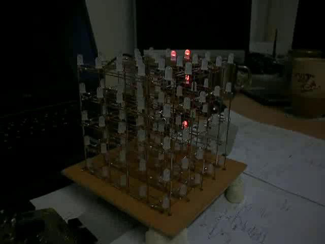
Although the animation can be played, the program is not yet complete. There is no support for the waiting list for animations, matrix keyboards and other peripherals (UART, I2C …). On the other hand, the code already written is ready for these edits. In the video below you can see “cube in action”.
FILE DOWNLOAD LINK LIST (in TXT format): LINKS-26231.zip


Circuit de cube LED RGB ATmega64
Le circuit de cube RVB Led est fondamentalement un véritable affichage 3D. Sa résolution est déterminée par le nombre de LED. Une plus grande résolution offre des effets plus fidèles, mais les exigences sur les LED RVB et les commandes augmentent avec le cube. Il est donc conseillé de choisir le bon compromis, entre difficulté et résolution. Voici la taille du cube 5, mais les LED sont RGB, ce qui rend les effets plus intéressants.
ATmega64 a été choisi comme MCU de contrôle, principalement en raison de la taille de sa mémoire flash (64 Ko). Il dispose également d’un grand nombre de broches, d’une interface matérielle PWM, UART, SPI et I2C. Parce que les LED RGB sont utilisées, nous obtenons 3 canaux de couleur. PWM est utilisé pour contrôler la lumière de chaque canal: R, G et B. Si tous les canaux de la LED sont «actifs», pratiquement toutes les couleurs peuvent être définies avec PWM. La limitation est ici principalement en termes de logiciel et qu’une combinaison PWM peut être définie pour une image 3D entière.
Étant donné que l’ensemble de l’appareil a été conçu pour être alimenté directement à partir d’USB sans avoir besoin d’une source externe, un convertisseur DC / DC a été ajouté à la conception. Cela apporte plusieurs avantages: