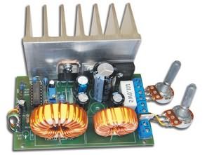
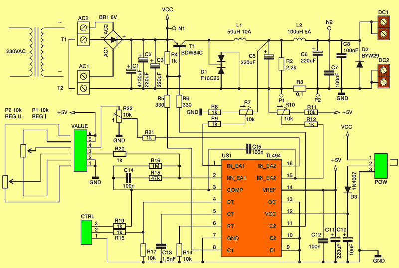
Switch Mode DC DC Adjustable Power Supply The TL494 system is the heart of the stabilizer. Elements C13-1.5NF, R14-10K set the frequency of the internal generator work to about 77 kHz. Comparator first, along with elements R7, R8, R9, R15, R16 and C14 are the output voltage stabilization circuit, which the value is regulated by the potentiometer P2. Comparator second with elements R10, R11, R12, R21 and R22 they constitute the current regulator circuit, whose value is set with potentiometer P1. The POW connector enables power supply of the control block and power block with the same voltage (1-2 shorted), or enables power supply control block from an external source, we attach them to pins 2-3, (2-plus, 3-mass).
This voltage should be in the range of 8 … 40 VDC. The CTRL connector allows switching off the stabilizer by providing a voltage of approx. 5 V on pin 2. The connector VALUE is used for regulation potentiometers as in the diagram. Elements T1 BDW84C, D1 F16C20 or BYW29, L1 and C5 form a typical impulse “step-down” converter. The other elements filter the input and output voltages. Lower range current regulation (0 … 0.5A) is difficult to obtain, therefore the scope of practical adjustment is … 0.5A 5A.
• 0 … 25V output voltage
• current limitation 0 … 5A (0.5A … 5A)
• smooth regulation of voltage and current
• possibility of remote switching off the stabilizer
• power supply: 24VAC or 2x24VAC
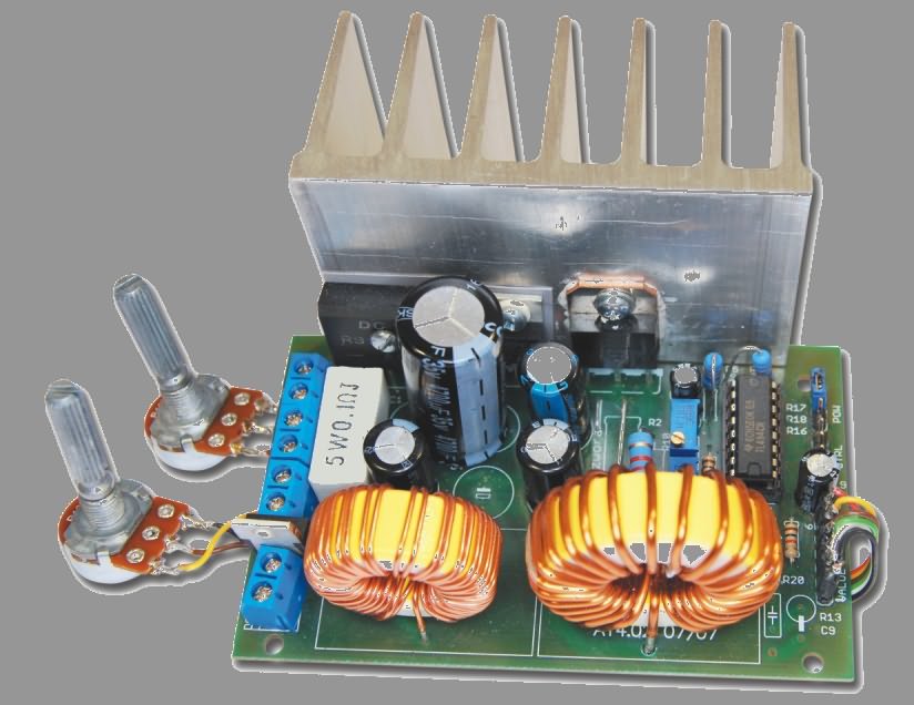
The system is powered directly from the transformer. Optimal for this purpose should have a 24 VAC secondary voltage or better 2 × 24 VAC and 150 W power. The transformer with a single winding is included as per the diagram. It should be remember to make a solid armature connecting T1 and T2 terminals. For transformer with double voltage, oerodek windings are connected to terminal T2, and clamp T1 is left free. After the first start-up, we have to set maximum voltage of 25 V with potentiometer R7 and maximum current with potentiometer R10. Potentiometer R22 set so that the current is evenly regulated in the entire rotation range of potentiometer P1. If the we expect a long-lasting high load on the stabilizer, we must necessarily use a fan, e.g. 10 × 10.
DC DC Adjustable Power Supply Circuit Schematic
![]()
FILE DOWNLOAD LINK LIST (in TXT format): LINKS-26223.zip


Mobile Robot Project MPU6050 ATmega328
Mobile Robot Project MPU6050 ATmega328
ATmega328, BLDC Motor, Gyroscope, accelerometer, inverse pendulum, I2C bus, Martinez V3, controller, modeling simulation, Matlab, Simulink, MPU6050 This work deals with the construction of two-wheeled mobile robot and subsequent creation drivers and controls for its sensors, motors and controller design. Management works on Arduino platform with ATmega328 processor. In the first place, the research is carried out.
The part of the thesis is a model part, where the simulation model of the system is created, its
linearization and subsequent controller design. It also contains a description of the production and construction of the robot body, description and functionality of used motors, description of all sensors and sensors and detailed description supplied PCBs. And finally, the program part where control is discussed motors, working with sensors and controller functionality. The result of this work is a functional application control and control of a two-wheeled unstable robot.
The two-wheeled mobile robot, whose center of gravity is above the wheel axis, behaves like an inverse pendulum that we see as a generally unstable system. Stabilizing such the system is achieved by maintaining a mechanical equilibrium, a condition in which the body’s axis is robot perpendicular to Earth’s acceleration.
Alimentation à découpage réglable 0.25V 0.5A TL494
Mode de commutation DC DC Alimentation réglable Le système TL494 est le cœur du stabilisateur. Les éléments C13-1.5NF, R14-10K ont réglé la fréquence du travail du générateur interne à environ 77 kHz. Le comparateur tout d’abord, avec les éléments R7, R8, R9, R15, R16 et C14 sont le circuit de stabilisation de la tension de sortie, dont la valeur est régulée par le potentiomètre P2. Comparateur second avec les éléments R10, R11, R12, R21 et R22 ils constituent le circuit régulateur de courant, dont la valeur est réglée avec le potentiomètre P1. Le connecteur POW permet l’alimentation du bloc de contrôle et du bloc d’alimentation avec la même tension (1-2 court-circuité), ou active le bloc de contrôle d’alimentation à partir d’une source externe, nous les attachons aux broches 2-3, (2-plus, 3 -Masse).