The operation of the thermometer circuit: If I explain the digital thermometer circuit made using the DS1621 temperature sensor. The operation of the circuit is as follows;
The numerical value taken from the heat sensor is sent to the microcontroller with the help of serial communication protocol I2C and the microcontroller prints this value to the LCD.
The DS1621 sensor, produced by the Dallas company, can measure between +125 and –55 degrees. There are two registers for the sensor to inform the high and low temperature values determined by the user.
The heat sensed from the environment is transferred to the microcontroller as 16 bits, and it is interpreted according to the written program and sent to the LCD.
The I2C serial communication protocol provides the communication between the microcontroller and the DS1621 IC. The microcontroller, which acts as the main function in the I2C protocol, communicates with the temperature sensors called satellites via RxD and TxD serial communication lines.
In the DS1621 integration, the SDA terminal is used with the P3_0 terminal of the microcontroller for data reception and transmission. The SCL tip of the microcontroller is used to generate the required clock pulse with the P3_1 tip of the microcontroller.
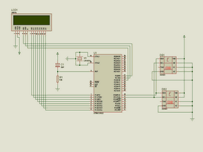
AT89C51 Thermometer Circuit Schematic

AT89C51 DS1621 Thermometer Circuit proteus isis simulation schematic and keil source code author: Şenol KAHRAMAN


USB Port Relay Control with Atmel Atmega8
6 relay control units can be made via the usb port usb drive computer program code and schema files are pcb circuit to regulate the supply 9-12 volt ac section there on the SPI and RS232 connections
In fact, with the computer relay to control a simple inexpensive circuit there, but (the PC and the Device Control) these circuits turned the computer port to question his instantaneous even in the relays pull leaves microcontroller used in the system prevent this problem can only be undertaken
USB Relay Control Project