
Arduino Controlled Adjustable Power Supply, Voltage Regulator. Input voltage is between 28V…35V. Output voltage is between 0 and 25V, output current is up to 3A. Output is protected against short circuit and current is fixed when the specified value is exceeded. There is also temperature protection against overheating of the output transistor.
Arduino Power Supply circuit is divided into two parts: Digital (Arduino, DAC, ADC, display and control buttons) and power. A 27V zener regulator is used to power the LM358 op-amp integrated circuit, which has a maximum supply voltage that allows it to be operated with a voltage higher than 32V.
The function of the regulation element is performed by the KT315G and KT825G transistors controlled by the op-amp; a voltage proportional to the output is given to the inverting input of the op-amp and a reference voltage is given to the non-inverting input. The KT825G transistor should be mounted on a heat sink with at least 400 m2 of space.
Arduino Regulated Power Supply
The digital part of the circuit consists of an ADC and a DAC, the output voltage is set by a 12-bit MCP4725 DAC, which is connected to the non-inverting input of the LM358 op-amp, the adjustment consists of 4096 steps (12 bits). The 16-bit ADC ADS1115 controls the shunt voltage, which does not exceed 300 mV at 3A current. The ADC and DAC are made in the form of ready-made modules controlled using the I2C bus. A software correction is applied to the output voltage to eliminate the effect of the shunt on the output voltage when the load current changes.
Temperature protection is implemented on the digital sensor (module) DS18B20, the sensor must be fixed to the KT825G transistor. If the transistor case temperature exceeds 85 ° C, the output voltage of the stabilizer will be turned off for 10 seconds. In addition, if the stabilizer output is short-circuited, the output voltage will also be cut off for 10 seconds. When the protection is triggered, a message is displayed on the screen.
The power supply of the digital parts of the Power Supply is provided by the 7805 regulator IC. Since the input voltage of the 7805 is higher than 30 V, the voltage is given through a 160 Ohm current limiting resistor. A small heat sink must also be installed.
Arduino Power Supply Control
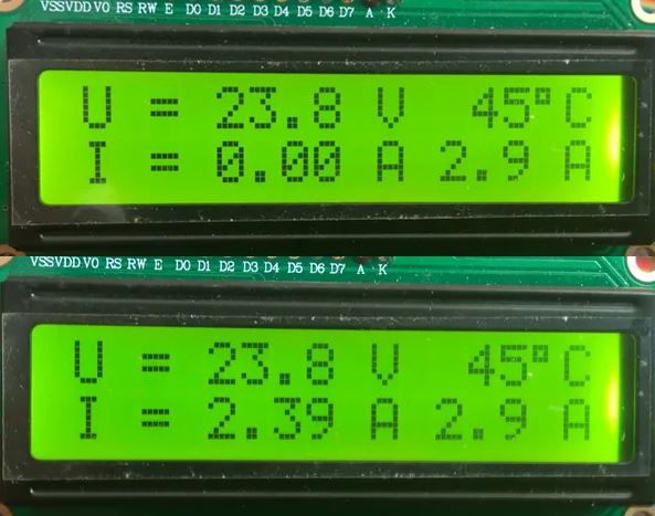
Arduino Power Supply control is quite simple, plus and minus buttons regulate the output voltage, when you hold down the current button, plus and minus buttons adjust the output current.
When the set current is exceeded, the output current stops increasing and stops at the set maximum current, while the voltage decreases. Voltage setting step 0.1V, current setting step 0.1A, minimum voltage value 0V, minimum current setting value 0.1A, current measurement with 0.01A resolution.
Arduino Power Supply Setting:
Press the “Plus” button, wait until the output voltage reaches the maximum value, measure the output voltage and specify it to the variable: u_max= 26.3 When using a shunt with a nominal value of 0.1 Ohm, current calibration is not required, but if the shunt has a large error, it is necessary to change the coefficient: kalib2 = 1.000
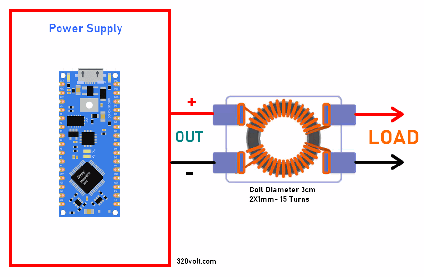
During the Arduino nano adjustable power supply tests, it was observed that when a low resistance load was connected, sparking occurred in the contact circuit and this sometimes caused the Arduino to freeze or display problems. It was understood that the resulting arc affected the digital part; in order to eliminate this negativity, an inductive filter should be added to the power supply output. The filter is made on a 3..4 cm diameter ferrite ring with a magnetic permeability of 2000 NN, two windings are wound together, the wire diameter is at least 0.8 mm, the number of turns is 10-15.
Source: rcl-radio.ru/?p=57730


