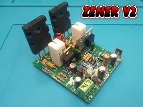
A more stable, stable version of the 100 Watt Mono Amplifier known as ZENER in Colombia. It can deliver 100W power with an 8 Ohm speaker and can also be used with a 4 Ohm speaker. Its noise is very low, and it does not make an explosion sound when opened. Even though I use SMPS as the power supply, there is no noise, hum etc. It was almost non-existent.
This configuration is known as a Semi-Complementary Amplifier. The amplifier is the mono version of the amplifier commonly known as “Zener” in Colombia. This name was given because there is a zener diode in the circuit that stabilizes the input differential pair.
Excellent stability, power and low harmonic distortion, an ideal amplifier circuit for use with Electric guitar preamps, Bass preamps or just voice-over with MP3, USB audio sources.
Circuit diagram


The amplifier circuit can deliver RMS 100W with an 8 ohm speaker. The capacitor at the audio input can be between 0.47uF and 4.7uF.
Make sure that the hFE values of the 2SA1015 transistors connected to the common emitter are close to each other. Their hFE should be around 170. If the HFE is higher than 180, the 2SA1015 is fake and there is usually a BIAS problem. (Provision; 2SA733)
The gain (hFE) of 2SC2229 transistors should not be greater than 190. Otherwise they may be fake. If 2SC2229 is fake or high gain, it will damage the output transistors. (Equivalents: 2SC1573, 2SC2271, 2SC1921)
The hFE value of TIP41, TIP42 transistors can be between 120 and 160. If they are far below or far above this value, they may be fake.
Original power transistors are low gain. It varies between 30 and 180 depending on the model. Measure the 2SC5200’s hFE and you should get a reading of 80 or less. These provide excellent performance. For 2SC5200 your hFE should be between 50 and 90.
With MJL21194 transistors, you can increase the transformer voltage to approximately 2×40 volts AC and get a little more power in the bass. You can use 35+35V AC transformer with 2SC5200 transistor. For full power, transformer power can be 150W or above. If you want to turn up the volume too much, you can use a lower power transformer.
You cannot get twice the power with a 4 Ohm speaker, there is an increase of around 20%, but the output transistors are overstressed. You can use full power MJL21194 transistors with a 4 Ohm speaker. In this case 20%. A little more power can be taken. More power is obtained with 2×40 volt AC. I did not do these tests.
Low power resistor tolerances are 5%, so I used whatever I had, but it would be better if you use 1/4 resistors with 1% tolerance.
The output filter is used so that the ZOBEL amplifier sees a resistive load at the output instead of the speaker’s inductive load. Its purpose is to prevent the passage of reverse currents produced by the speaker. These may damage the amplifier outputs. It also helps reduce the possibility of high frequency oscillation. L1 Coil is made by winding 12 turns of 1mm coated wire on a 9mm rod.
Power Supply Circuit Diagram


I prepared a small PCB for DC Rectification, filter capacitors can be between 63V 4700uF…6800uF. Capacitor diameter max. 25mm. You can use this circuit in different amplifier circuits.
I prepared the new PCB design with Sprint Layout 6 program. The PCB size is quite small, 51.7×58.4mm PCB single-storey, you can print PCB at home without any difficulty. If you are going to have PCB made in China, I added a path to the sections where wire jumps are made without the top layer. If you are going to make a printed circuit at home, do not select the C1 layer when printing.
The voltages that should be at certain points in the amplifier’s diagram were shown, and I also added the PCB drawing I prepared. These voltages allow us to understand whether the system is working properly or not.
For example, there should be 0.7 volts where the two emitters of the A1015 meet. If not, it may be inaccurate, fake or there may be large discrepancies between their earnings. BIAS measurement on TIP41’s base should give 0.7V. Of course, it is quite difficult to achieve a completely symmetrical BIAS in this amplifier, and even more difficult when you take into account the terrible quality of today’s transistors.
However, if the A1015 measures 0.7V and the output measures 0V and the other sections measure between 0.4V and 0.8V, the amplifier will work fine and without problems. So don’t panic if you can’t achieve perfect BIAS. However, if the voltage difference is exaggerated, we need to check whether the transistors are original and of high quality. An exaggerated BIAS mismatch can produce excessive heat in the output transistors and, in some cases, bad sound.
Note: I have never had any problems, but if the BIAS voltages are not regular even though everything is correct, try installing a trimpot instead of the 33-ohm resistor and making adjustments.
Before starting the measurements of the amplifier, connect a 220v 60w lamp to one of the 220v inputs of your transformer. In this way, if there is a problem, you can protect the circuit or the card without major damage. If the measurements are correct and there are no overheating parts, you can disassemble the lamp and proceed with the sound tests.
ZENER V2 Amplifier Wiring Diagram

Finally, there are two changes in the version of the Zener amplifier that uses 4-ohm speakers: 0.33-ohm 5w resistors are used instead of 0.47-ohm 5w resistors. The serial resistor and 1N4007 diodes from the collector of the Q5 transistor and the 33-ohm resistor in the section going to the base of the Q7 transistor have been replaced. I do not know if there is a difference in the operation compared to the other connection. I did not see any problems. If necessary, their places can be changed without making changes to the PCB.
8-OHM Speaker

4-OHM Speaker

Source: videorockola.com
PCB and source files of ZENER V2 quasi Complementary 100W Amplifier Circuit;
Password: 320volt.com
Published: 2023/10/18 Tags: audio amplifier circuits, transistor amplifier
Hi
Excellent projects!
Where can I get a full DIY kit for these amplifiers and power supply?
I am in Australia.
Hi, No sale. All necessary files have been shared. you have to do it yourself DIY 🙂