I implemented the “200watt 300watt 400watt 500watt Amplifier Circuit” project that I shared years ago. Actually, I wanted to do it when I shared it, but quiescent current adjustment, measurements etc. I don’t like it 🙂 But after receiving occasional feedback about this amplifier for a long time, I wanted to try it. Since the PCB design is large, I designed a modular PCB only for the driver.
In the source document, detailed information is given about quiescent current measurements, as well as other details. I started working thinking it would probably work. The circuit worked smoothly on the first try.
I mentioned the details about quiescent current measurements in the video. Apart from this, I had a problem with the control integrated. TL071 opamp is used in the circuit, but the voltage of TL071 and Zener regulator was collapsing excessively, the integrated was defective or fake, so I used a 741 opamp instead, there was no voltage collapse and the circuit worked.
I remembered the feedback of our reader who made the “100W 400W Amplifier Circuit IRFP240 IRFP9240 Mosfet” circuit. He also experienced the same problem and said that he could run the circuit with 741 opamp without any problems.
I know these projects are solid, most likely fake TL071 opamps are quite common, maybe there is a compatibility problem compared to the old production, I don’t know…
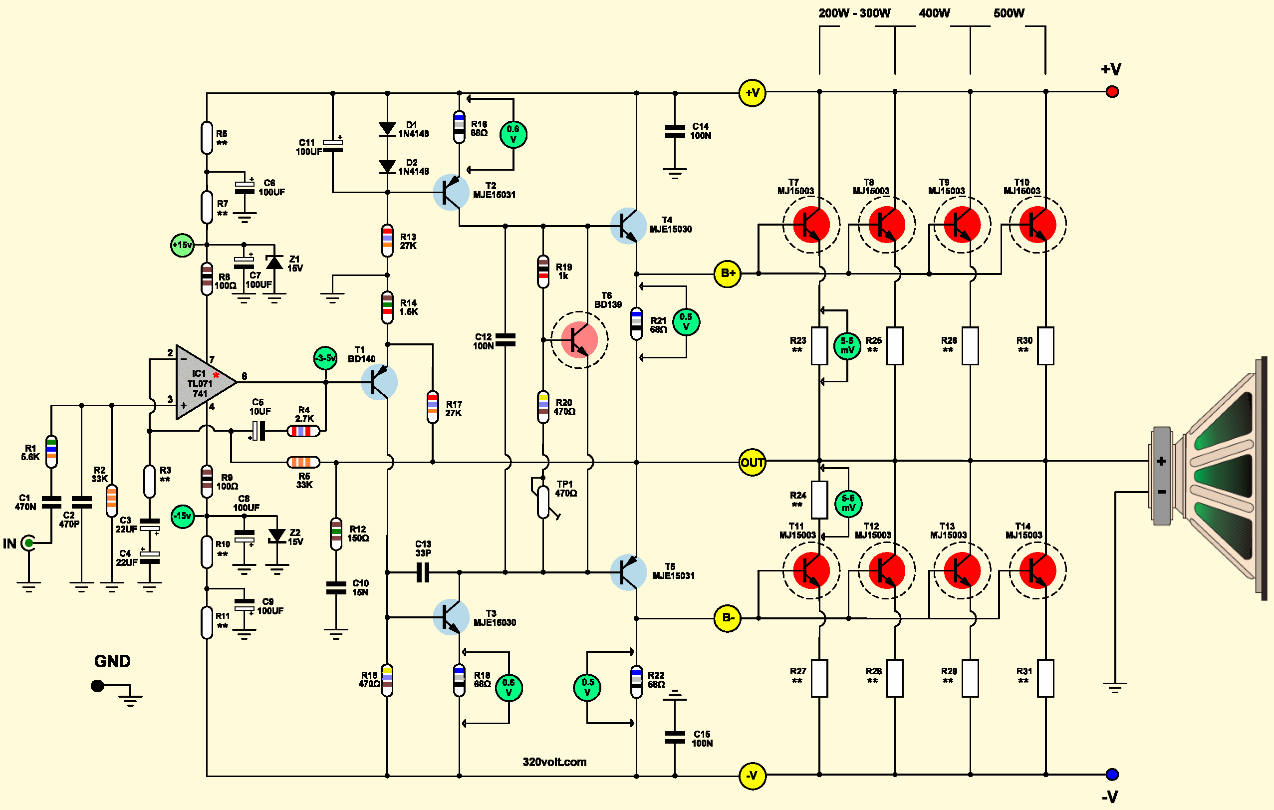
500W Amplifier Circuit Diagram
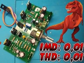
As always, I used bass and mid-range cabinets in the tests. Especially the bass was very good, even though there was no filter, it gave a good sound in the bass cabin. Since I did not have an MJ15003, I used 2N3773 transistors, original Toshiba production. Most of the amplifiers that used TO3 case transistors had 2N7337 (in the past).
I prepared PCB drawings for TO3 and TO247 transistors (checked, not tested). The transistor group is 4X, 6X and 8X. You can use MJL21194 or MJW21196 for the TO247 case. Actually, 2N3773 for TO3 or 2SC5200 for TO247 can be used, but max. It is necessary not to use it at high power, or the number of transistors should be increased by one, in which case the driver transistors may need a cooler, it is necessary to try… Use thermal paste and insulators in the cooler assembly of the transistors.
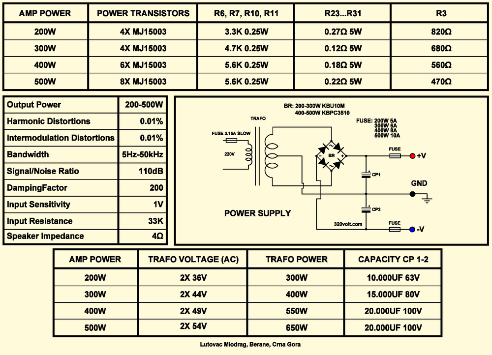
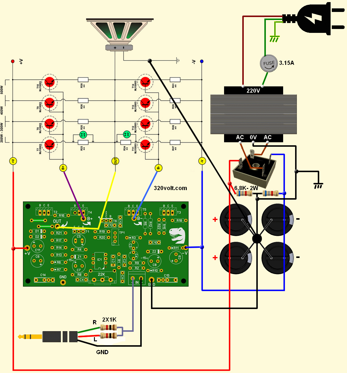
Amplifier Wiring Diagram
I prepared the diagram below for the power supply and audio connection. If you are going to use two channels, you do not need to use 1k resistors at the audio input. You determine transformer and capacitor values according to power.
It would be beneficial for you to use the speaker protection circuit, so I added the PCB drawing to the file. For capacitor values of 10000uf…20000uf, you can use lower value capacitors by connecting them in parallel.
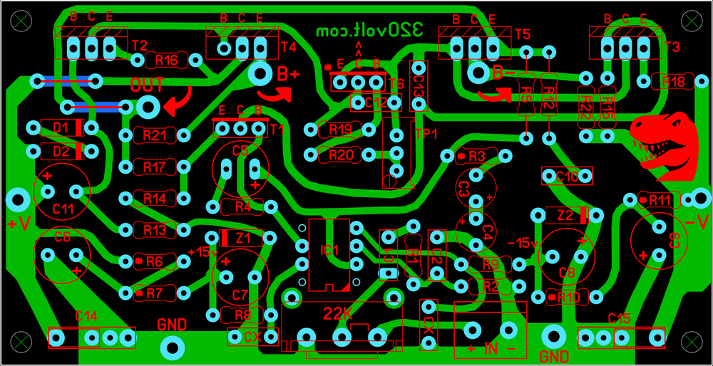
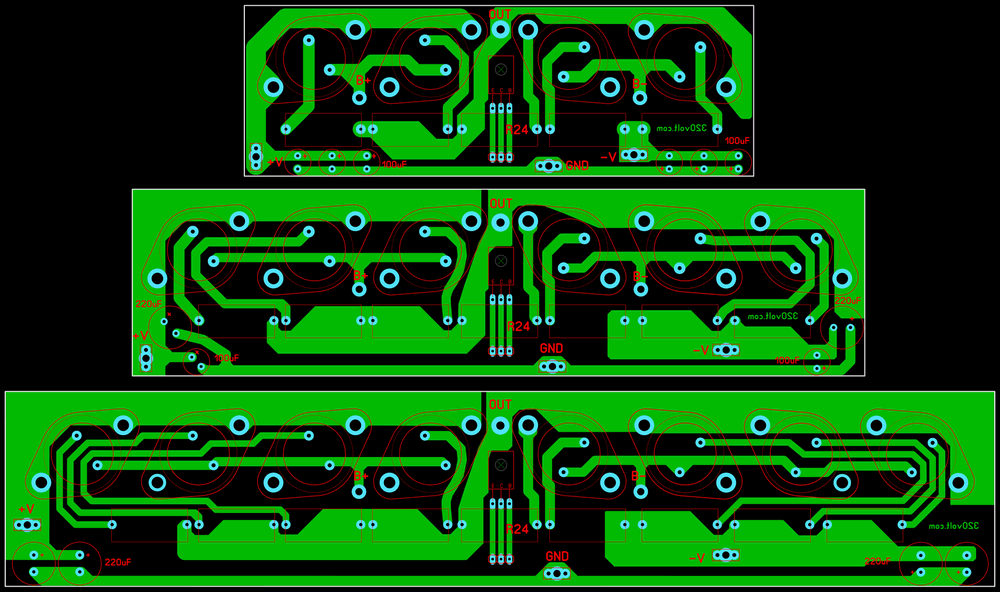
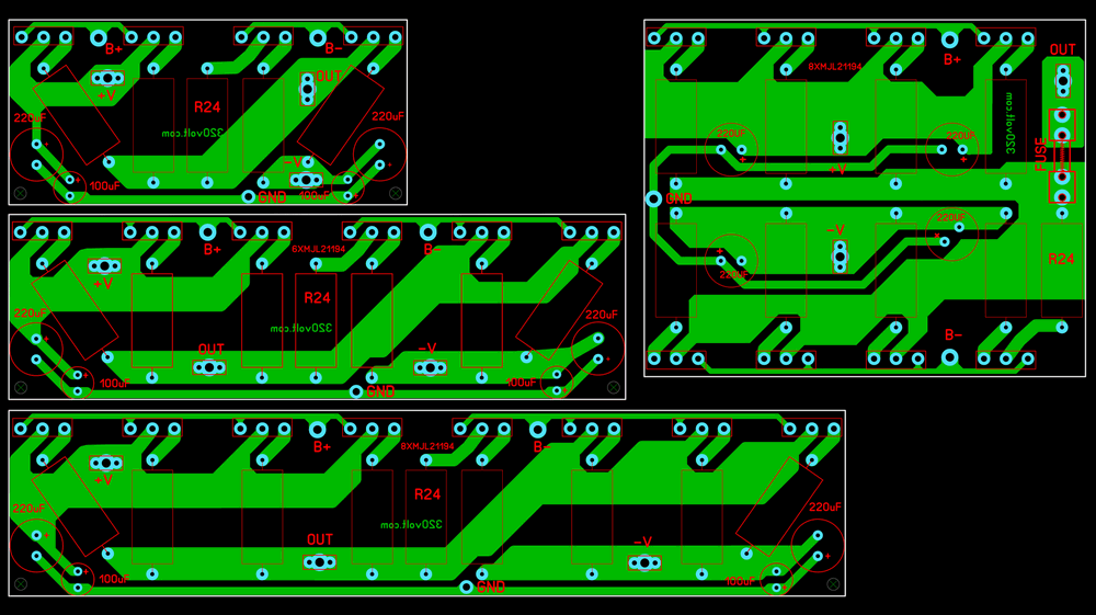
TO3 and TO247 Transistor PCB drawings
Other details; The many years of use and production of this amplifier prove in many cases the very high quality of both the construction and the performance of this amplifier. The amplifier can be built with powers from 100 to 800W for speaker impedances of 2 to 8 Ω, with the scheme given and with appropriate changes in the ratings of some components.
The input sensitivity of the amplifier is 1V and is determined by the R3 resistor. By increasing the value of resistor R3, the input sensitivity can be reduced and vice versa. The minimum value of resistor R3 is 330 Ω.
Connect the amplifier to the power supply through 100 Ω, 2-5w resistors and measure the voltage drop on them, it should not be higher than 3V, otherwise some errors have occurred in the amplifier due to poor soldering, incorrect installation of elements, incorrect installation of one of the semiconductors or similar errors.
After finding and eliminating the defects, repeat procedure a and measure the voltage drops across their resistors. Then check the Op amp supply voltages on pins 4 and 7 (-15v and +15v). There should be approximately -3.5v voltage on pin 6 of the op amp IC. The voltage drop across R16 and R18 should be around 0.6v.
Turn the TP1 trimmer all the way to the left. Measure voltage drops across R21 and R22, these should be less than 0.5v, otherwise reduce R19 to 820 Ω. Now connect the output transistors and adjust the quiescent current by turning the TP1 trimpot to the right, the voltage drops across resistors R23 and R24 will be 5 times greater (in mv) than the value of the resistors (for example, for resistors of 0.12 Ω the voltage drop should be 6mv). In this way, we set the quiescent current per output transistor to 5mA. For voltages below +/- 60v, BD 243C/BD 244C can be used instead of MJE15030 MJE15031.


Can I get amp pcbs published here
https://ibb.co/zFphD4z