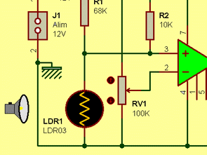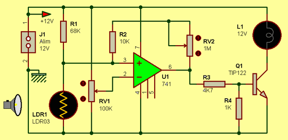
with the LDR circuit diagram keep on working as a dimmer switch. Circuit, four resistors, a opamp, two potentiometers, an LDR, a switching transistor and consists of a lamp. Circuit, the value of resistor R1 ARD is directly proportional to the internal resistance of the 6-12V works as a voltage divider.

Ldr1 depending on the internal resistance , potentiometer RV1 ldr1 fall on the task according to the degree of accuracy for the amount of light is used. RV1 is subject to a voltage divider . Therefore, the resistor LDR1 and R1 divided by the value of the material , divided by the resistance value RV1 is constantly compared by U1 . Here RV1 potentiometer 6V and that ldr1 too dark Assuming that , ldr1 the internal resistance will be higher U1 ‘s inverting input on the voltage , 6V a value close to or a little more than take a value from the U1 (741 opamp) output will be a positive voltage .
By triggering it L1 Q1 through R3 will provide the lighting . L1 emitting light with a certain reduction in the internal resistance of ldr1 will be observed that this would attract the opamp output to 0V going to cut transistor T1 , L1 will flash. Alone to be considered is that, assuming that the resistance R4 on the opamp output from a constant voltage of transistor Q1 will be concerned to go to slaughter will be hampered. R4 resistance, voltage of transistor Q1 chassis will draw on the oval . RV2 potentiometer 741 OpAmp will change the gain will react against . If the resistance of the potentiometer RV2 is large , the opamp as a comparator to operate , will operate as an amplifier is small while .
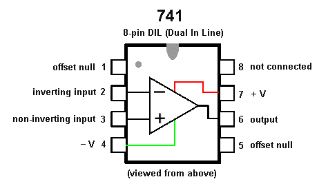
741 Op Amp Pinout

Published: 2012/06/09 Tags: analog circuits projects, simple circuit projects
Super Flyback Driver Circuit UC3844
Author “Super final version flyback driver,” he said, but not so super stable than other simple flyback driver to control at least 555 UC3844 SMPS control IC is used instead. Flyback MOSFET driver circuit used irfp260, 12:18 ohm resistor connected to the source through the legs made of current limiting.