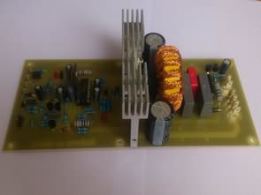
IRS2092 Subwoofer 400W Claas D Amplifier Circuit.The main part of this protection circuit is a transistor FET which is connected in the power supply branch amplifier integrated circuit IRS2092. When applying a positive voltage to the control electrode of the transistor, the ground power supply voltage and the comparator halts the modulation process. The transistor FET is switched on the circuit that brings together a number of protections. One of them is check the power supply, which detects whether the supply voltage is in the range of 68 to 100 volts. If this the condition is not met, the class d protection will react. Additional protection is temperature. Circuit controls the voltage on the thermistor, which is located on the heatsink of the power switching Mosfet. Last class d amplifier protection detects the amplified audio signal at the output of the amplifier and responds when congestion or limitation.
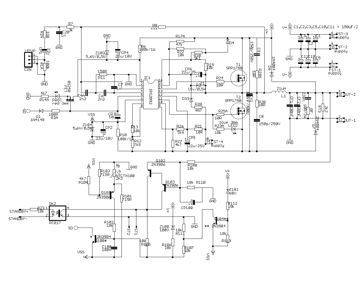
400W Claas D Schematic
As the switches in the power section of the amplifier working in class D it is possible to use several
different types of power transistors. From the point of view of manufacturing technology and physical nature the principle of operation offers us three basic types of transistors: bipolar, IGBT and MOSFET. Bipolar transistors are unlike MOSFET driven from the shock and the excitation of the transistor meeting the power demands for the proposed amplifier would be performance-demanding.
The proposal of the amplifier in class D After studying and evaluating the different types of modulation I have chosen because of the simplicity of the pulse-width modulation (PWM), which is for use for a subwoofer of its qualities quite sufficient. Distortion is when the frequencies of the bass bandwidth do not translate nearly as well as in the zone of the mids or treble. The design of the amplifier from discrete components would be very costly. The modulator requires the use of a precision generator of triangular signal, several high-quality operational amplifiers and logic gates. Due to the savings in finance it is better to use an integrated type of wiring, which reduces the cost to a quarter. I chose integrated circuit IRS2092 from the company International Rectifier[8]. This circuit includes the modulator, driver half-bridge output stage and requires the use of only few external components. Furthermore, this integrated amplifier overcurrent protection and the function of removing pop when turning on and off.

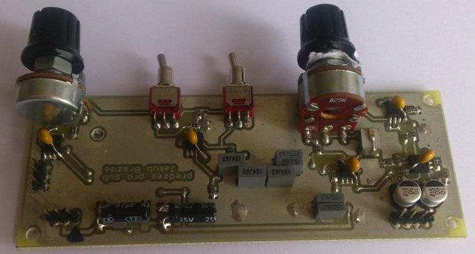
Class D Subwoofer Pre-Amplifier Circuit

Subwoofer filter circuit is a device which is used for reproducing sound of low frequency. This is a frequency from the lower edge of the acoustic band up to the top of the dividing frequency, which is set in the range of 60Hz to 250Hz. Above this frequency no sound reproduce other speakers in the ozvučovacím system. In stereo systems, even the systems of multiple channels is subwoofer one joint while maintaining the qualities of the reproduction. It uses a phenomenon that a person is capable of wrong or even is not able to determine whence the sound of low frequencies comes. When using a common subwoofer can be a speaker for the other parts of the sound band rated for less power and therefore cheaper. Active Class D subwoofer filter circuit
![]() Class D 400W Amp circuit pcb schematic all files alternative links:
Class D 400W Amp circuit pcb schematic all files alternative links:
FILE DOWNLOAD LINK LIST (in TXT format): LINKS-25712.zip


240W Electronic Ballast Circuit IR2104 ATmega48 Controlled
IR2104 240W Fluorescent tube Ballast Circuit. Work was designed an electronic ballast for starting six fluorescent lamps with a total output of 240W with integrated dimming-controlled analog input and button. Priority is set to control voltage. If the input voltage less than 0.5 V, tests with the push of a button. Measuring the voltage at the input is constant, and when voltage detection is higher than 0.5 V, occurs to the start of the fluorescent lamps and the subsequent setting of the intensity of the brightness-dependent the inlet voltage, while when 5 V is set to the maximum intensity. When the control voltage it was necessary to introduce hysteresis due to the constant changing frequency. This hysteresis has been set step ±50 Hz. The resolution of the transfer of voltage to frequency is therefore in the set range of 80 steps.
400W Klasse D Subwoofer Verstärker Schaltung IRS2092
IRS2092 Subwoofer 400W Klasse D Verstärker-Schaltung.Der Haupt-Teil diese Schutzschaltung einen transistor, FET verbunden ist, in die Netzteil-Zweig-Verstärker der integrierten Schaltung IRS2092. Beim anlegen einer positiven Spannung an der steuerelektrode des Transistors, die Masse der Versorgungsspannung und der Komparator hält das Modulationsverfahren. Der transistor FET ist eingeschaltet, die Schaltung, die zusammen bringt eine Reihe von Schutzmaßnahmen. Einer von Ihnen ist, überprüfen Sie die Stromversorgung, die erkennt, ob die Versorgungsspannung im Bereich von 68 bis 100 Volt. Wenn diese Bedingung nicht erfüllt, wird die Klasse d-Schutz reagieren werden. Zusätzlicher Schutz ist die Temperatur. Schaltung steuert die Spannung am thermistor, die sich auf die Kühlkörper der power switching Mosfet. Letzte Klasse-d-Verstärker Schutz erkennt das verstärkte audio-signal am Ausgang des Verstärkers und reagiert, wenn Staus oder Einschränkung.