Charger Circuit LM393 op-amp based on the computer’s USB port with 5 volts on 2 AA NiMH, NiCd batteries can be recharged. Charging current of 470 pcb circuit drawing and detailed information have.

During charging, R1, R2, and R4 form a three-way voltage divider which yields about 1.26V at the non-inverting input of Z1a (pin 3, Vref). TR1 is a thermistor that is in direct contact with the cells being charged. It has a resistance of 10k at 25°C (77°F), which varies inversely with temperature by about 3.7% for every 1C° (1.8F°). R3 and TR1 form a voltage divider whose value is applied to the inverting input (pin 2, Vtmp). At a temperature of 20°C (68°F), TR1 is about 12k, which makes Vtmp about 1.76V.
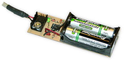
The charger in this project is designed to charge two AA NiMH or NiCd cells of any capacity (as long as they are the same) at about 470mA. It will charge 700mAh NiCds in about 1.5 hours, 1500mAh NiMHs in about 3.5 hours, and 2500mAh NiMHs in about 5.5 hours. The charger incorporates an automatic charge cut-off circuit based on cell temperature, and the cells can be left in the charger indefinitely after cut-off.


Size: 3.8″L x 1.2″W x 0.7″H (9.7cm x 3.0cm x 1.5cm).
Cells: Two AA, NiMH or NiCd
Charging Current: 470mA
Charge Termination Method: Battery Temperature (33°C)
Trickle Current: 10mA
Power Source: Desktop, Laptop, or Hub USB port
Operating Conditions: 15°C to 25°C (59°F to 77°F)
| Current Battery | Charging Time |
|---|---|
| 700mAh NiCd | 1.5HRS |
| 1100mAh NiCd | 2.5HRS |
| 1600mAh NiMH | 3.5HRS |
| 2000mAh NiMH | 4.5HRS |
| 2500mAh NiMH | 5.5HRS |
Source: stefanv.com USB Battery Charger schematic pcb Alternative link:


12V to 15V DC DC Converter Circuit MC34063
DC to DC converter circuit 12 volt input 15 volt 2 amp converter circuit MC34063 output power raises Step-Up-Down and Inverting can function as integrated switching is used.
DC / DC converter circuit general characteristics;
Input voltage: 10. 14volt
Output voltage: 15 volts, 2 amps
Yield: 80%
USB-Ladegerät Nimh Nicd
Ladeschaltung LM393 Operationsverstärker basierend auf dem USB-Anschluss des Computers mit 5 Volt an 2 AA-NiMH-NiCd-Batterien kann aufgeladen werden. Ladestrom von 470 pcb schaltung zeichnung und detaillierte informationen haben.
Während des Ladevorgangs bilden R1, R2 und R4 einen Dreiwege-Spannungsteiler, der am nicht invertierenden Eingang von Z1a (Pin 3, Vref) ungefähr 1,26 V liefert. TR1 ist ein Thermistor, der in direktem Kontakt mit den zu ladenden Zellen steht. Es hat einen Widerstand von 10 k bei 25 ° C (77 ° F), der umgekehrt mit der Temperatur um etwa 3,7% pro 1 ° C (1,8 ° F) variiert. R3 und TR1 bilden einen Spannungsteiler, dessen Wert an den invertierenden Eingang (Pin 2, Vtmp) angelegt wird. Bei einer Temperatur von 20 ° C (68 ° F) beträgt TR1 ungefähr 12 k, was Vtmp ungefähr 1,76 V ergibt.
Das Ladegerät in diesem Projekt dient zum Laden von zwei AA-NiMH- oder NiCd-Zellen mit einer Kapazität von etwa 470 mA (sofern diese gleich sind). Es lädt 700 mAh NiCds in ca. 1,5 Stunden, 1500 mAh NiMHs in ca. 3,5 Stunden und 2500 mAh NiMHs in ca. 5,5 Stunden auf. Das Ladegerät verfügt über eine automatische Ladeabschaltung, die auf der Zelltemperatur basiert. Die Zellen können nach dem Abschalten unbegrenzt im Ladegerät belassen werden.