Design of controllable current source, which will be used to control the brightness of the power LEDs. It is intended to use fifteen PWM outputs from Arduino for management of fifteen resources. This application will be used to calibrate the camera.
That’s why it is minimum ripple current through the LEDs is required. At the beginning of this work will be described Arduino and graphical environment Delphi 7. Using the application it will set the required values on the Arduino PWM outputs. Arduino is an electronic platform based on simple hardware and software and its communication with Microsoft Delphi application is described here.
Next, switching and linear current sources and their properties will be described. Current sources are sources that maintain a constant current. To control the current of the LEDs are predominantly They use LED drivers, so one concept is designed with an integrated switching power supply or LED driver TPS92513.
The aim of this work is to design and implement several concepts of controllable current sources
with the least current ripple, comparison and selection of the most suitable circuit. Part of the work will be the basis for making these circuits, ie wiring diagrams and drawings printed circuit board. The proposed source will be used to control the brightness of diodes with different VA characteristics, therefore a switchable divider will be placed on the control input of each circuit to provide limitations current of 250 mA, 150 mA and 50 mA.
Schematic TL494 Power Led Driver Circuit

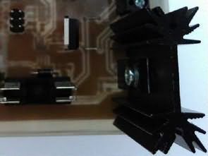
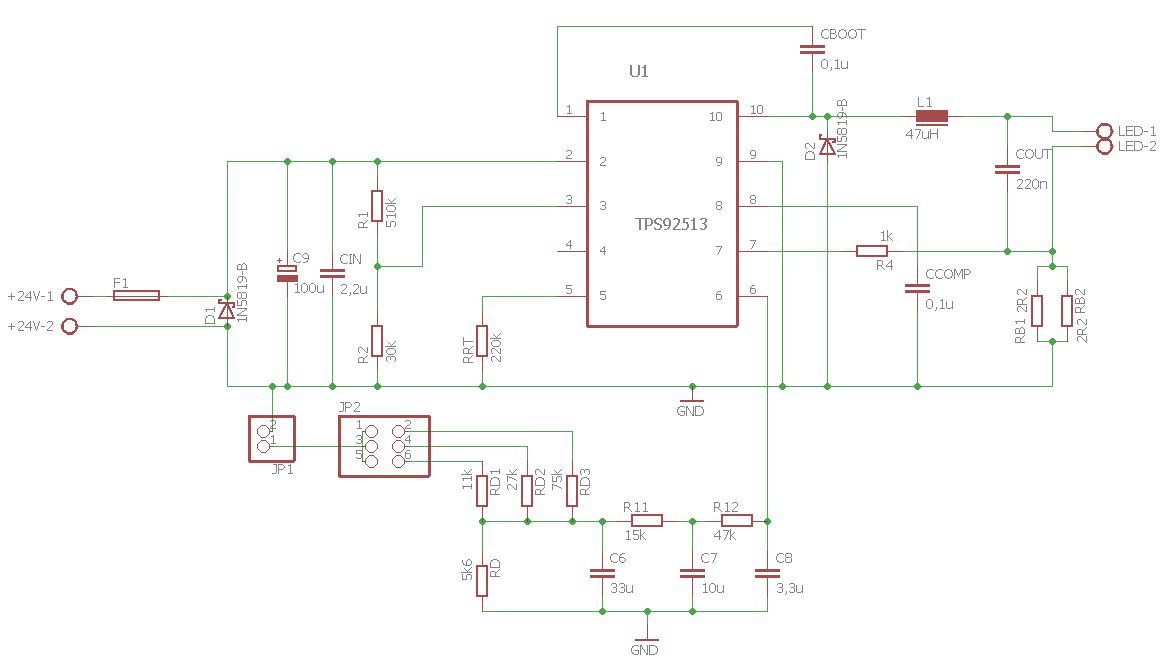
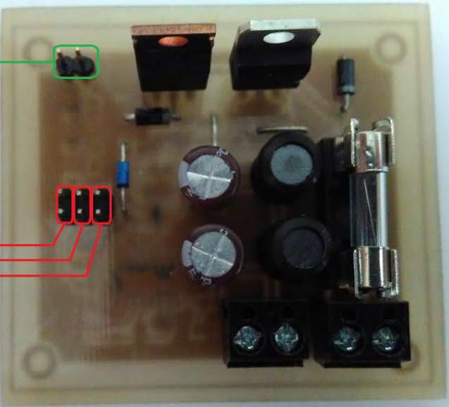
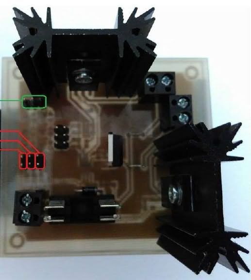
Schematic TPS92513 Power Led Driver Circuit
Lower ranges are used for larger ones distinction. The Arduino analog outputs have an eight-byte resolution, which is why we use it range 0 – 50 mA, where it is possible to adjust the current in steps of 0.2 mA. It is in the range of 0 – 250 mA step 1 mA. For comparison, a current source operating in linear mode, a current source operating will be proposed in switching mode and a switching power supply based on the above mentioned LED driver. All these circuits will be measured in all ranges and evaluated.
![]()
FILE DOWNLOAD LINK LIST (in TXT format): LINKS-26262.zip


TPS92513 TL494 Circuit de pilotage à alimentation électrique
Conception d’une source de courant contrôlable, qui sera utilisée pour contrôler la luminosité des LED d’alimentation. Il est prévu d’utiliser quinze sorties PWM d’Arduino pour la gestion de quinze ressources. Cette application sera utilisée pour calibrer la caméra.
C’est pourquoi un courant d’ondulation minimal à travers les LED est requis. Au début de ce travail sera décrit Arduino et l’environnement graphique Delphi 7. En utilisant l’application, il définira les valeurs requises sur les sorties Arduino PWM. Arduino est une plate-forme électronique basée sur du matériel et des logiciels simples et sa communication avec l’application Microsoft Delphi est décrite ici.
Ensuite, les sources de courant de commutation et linéaires et leurs propriétés seront décrites. Les sources de courant sont des sources qui maintiennent un courant constant. Pour contrôler le courant des LED sont principalement Ils utilisent des pilotes LED, donc un concept est conçu avec une alimentation à découpage intégrée ou un pilote LED TPS92513.