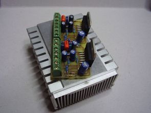
the TDA7294 200W can power on the circuit with a bridge connection 2 TDA7294 is used for the CPU cooler mounted and very small size of the PCB can be used. 2x100w 200W mono output can be used as single or two-channel stereo. All jumpers all the jumpers on the circuit short circuit open circuit 2x100w 200W mono when stereo is
the tda7294 200W amplifier is symmetric power supply 2x12v ….. You can use the transformer 2x24v 200w


Note: Drawing PCB did not do very thick in the power supply line flowing roads, the chassis, the solder coating on the output section has benefits. In this way, you can prevent future copper in oksitlenmesini ..
22UF on the circuit, 10uF, 50v or 63v 470nF capacitors used
200W TDA7294 amplifier PCBs, connectors, materials, layout drawings


Symmetrical power supply circuit
In addition, you can use TDA7294 and a lot of similar symmetrical feed circuit of the amp pcb circuit 2x 10.000uf promise in çizimini 63v capacitor and diode bridge can be used in addition to 10 amp fuse holder KBU10M load resistors and 2 LEDs have 100nF. As the power amplifier circuit is not very thick flowing roads TDA7294 circuit than enough, but if you use a high-powered applications that use PCBs or thinner copper plaque with the cover of this circuit solder Paths


FILE DOWNLOAD LINK LIST (in TXT format): LINKS-19290.zip


Solar Panel Battery Charger Circuit 100W
Solar panel charging circuit with the highest lead acid battery can be charged 100ah 13.5 volts regulator and 12.5 v 14.2 volts “Hysteresis” circuit. Solar Panel + entry in the section that you can use the SBL3040 or MBR3040 in your area for the diode or diodes, high power output 5v pc power sources used in this çıkmasıda will do the job.
Note: printed circuit board on the value of the resistors that are not specified in the application, are they included in a drawing for the delicate adjustment is not being used. Solar panel battery charger circuit, but the first version of the Hysteresis for relay relay used in the second version more current consumes irf9540 P-channel mosfet is used, it is better to make a second version of the
TDA7294 Verstärkerschaltung Kleine Leiterplatte
Der TDA7294 200W kann den Stromkreis mit einer Brückenverbindung einschalten. 2 TDA7294 wird für den CPU-Kühler verwendet, und es kann eine sehr kleine Größe der PCB verwendet werden. 2x100W 200W Mono-Ausgang kann als Einzel- oder Zweikanal-Stereo verwendet werden. Alle Jumper alle Jumper auf dem Schaltkreis Kurzschluss offen 2x100W 200W Mono, wenn Stereo ist
Der Tda7294 200W Leiterplatte Verstärker ist symmetrische Stromversorgung 2x12V … .. Sie können den Transformator 2x24V 200W verwenden
Anyone try this circuit. I want to build this amp design and close all jumper for bridge subwoofer.
Thank you
Does this design work. I wanna use for bridge subwoofer
Schematic of this design available?
Hi
Can i use 18k instead of 22k resistors?